


Courtesy-light-delay-switch

Description: This circuit maintains the internal light for approximately one minute after the car doors are closed. When the door contacts open, a positive voltage pulse is applied to the base of transistor T1. This action activates T1, which in turn deactivates T2 and allows the charging of a 10 µF capacitor. Transistor T3 is then activated, keeping the internal light on. The capacitor discharges over the course of one minute when the circuit returns to its original state.
The circuit operates as a delay mechanism for the internal light in automotive applications, ensuring that the light remains illuminated for a specified duration after the doors are closed. The primary components include three transistors (T1, T2, and T3) and a capacitor (C1, rated at 10 µF).
When a car door is closed, the door contacts break the circuit, sending a positive voltage pulse to the base of T1. This pulse turns T1 on, allowing current to flow from the collector to the emitter, which subsequently turns off T2. With T2 deactivated, the path is cleared for C1 to charge. The charging of C1 creates a voltage across it, which is used to turn on T3. Once T3 is activated, it maintains the current flow to the internal light, keeping it illuminated.
The design of the circuit ensures that the internal light remains on for a duration of approximately one minute, as the capacitor C1 takes this time to discharge. The discharge rate is determined by the capacitor's value and the load presented by the internal light circuit. Once C1 has fully discharged, T3 turns off, ceasing the current to the internal light and returning the circuit to its original state.
This circuit is an example of a simple yet effective delay timer utilizing basic electronic components. It is particularly useful in enhancing user experience in vehicles, providing convenience and safety by ensuring visibility after exiting the vehicle.This circuit holds on the internal light for approximately one minute after the car doors are closed. When the door contacts open, a + VE pulse is applied to the base of Tl. This transistor turns on, turning off T2 and charging the 10-llF capacitor. T3 turns on, holding on the internal light. The capacitor takes one minute to discharge when the circuit reverts to its original state.
The circuit operates as a delay mechanism for the internal light in automotive applications, ensuring that the light remains illuminated for a specified duration after the doors are closed. The primary components include three transistors (T1, T2, and T3) and a capacitor (C1, rated at 10 µF).
When a car door is closed, the door contacts break the circuit, sending a positive voltage pulse to the base of T1. This pulse turns T1 on, allowing current to flow from the collector to the emitter, which subsequently turns off T2. With T2 deactivated, the path is cleared for C1 to charge. The charging of C1 creates a voltage across it, which is used to turn on T3. Once T3 is activated, it maintains the current flow to the internal light, keeping it illuminated.
The design of the circuit ensures that the internal light remains on for a duration of approximately one minute, as the capacitor C1 takes this time to discharge. The discharge rate is determined by the capacitor's value and the load presented by the internal light circuit. Once C1 has fully discharged, T3 turns off, ceasing the current to the internal light and returning the circuit to its original state.
This circuit is an example of a simple yet effective delay timer utilizing basic electronic components. It is particularly useful in enhancing user experience in vehicles, providing convenience and safety by ensuring visibility after exiting the vehicle.This circuit holds on the internal light for approximately one minute after the car doors are closed. When the door contacts open, a + VE pulse is applied to the base of Tl. This transistor turns on, turning off T2 and charging the 10-llF capacitor. T3 turns on, holding on the internal light. The capacitor takes one minute to discharge when the circuit reverts to its original state.
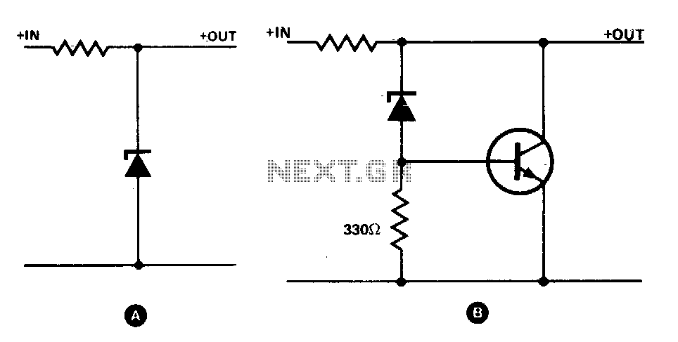
Transistor increases zener rating
The simple zener shunt in configuration A may not handle sufficient current if the zener diode available is of low wattage. A power transistor will perform most of the work for the zener as illustrated in configuration B. Once the...
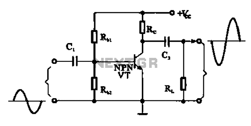
A common emitter amplifier
A common emitter amplifier is a total pole amplification circuit structure featuring a key emitting device. This circuit refers to the emitter of the input signal and the output signal connected to a common ground, forming the basis of fundamental...
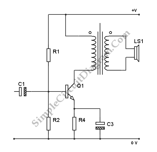
Transistor Class A Power Amplifier
The transistor is biased in Class A, meaning that the collector current flows continuously. This current can vary, increasing or decreasing in response to the input signal.
In a Class A biasing configuration, the transistor operates in the active region for...

Data Switch with LED
Just to prove that transistors can also be useful in logic situations; this is a data latch and indicator which also is a data switch and has a bidirectional input/output port which can be read or switched. If the second...

Tickler oscillator circuit
When the circuit is initially powered, neither transistor is activated, resulting in high base voltages for both and a tendency to turn on. Due to slight asymmetries, one transistor will activate first, leading the circuit into one of its states...

Mini Logic probe with transistor circuit
This logic probe circuit is designed for checking voltage levels in TTL circuits. It receives signals from the circuit being tested and indicates whether the logic level is high or low. When the input voltage at the probe tip exceeds...

Intermittent start and stop cycle control circuit Five of a
The circuit depicted in Figure 3-80 is responsible for controlling a portion of the transistor multivibrator. A multivibrator serves as a robust positive and negative feed-forward amplifier, consisting of two branches that are interconnected through a coupled RC timing circuit,...

Transistor Circuits
It had been a little over a decade since the invention of the transistor when this article appeared in the August 1959 edition of Popular Electronics. Transistors were still a mystery to many, including engineers, technicians, and hobbyists. Author James...
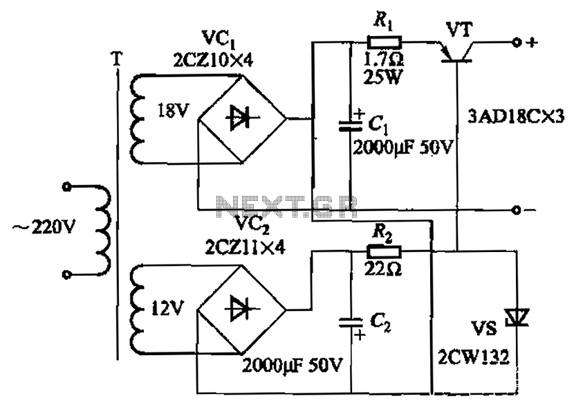
Steady flow of power transistor circuit
Characterized by a steady flow of power when the power supply voltage fluctuates or the load changes, this circuit maintains a constant load current. The output current of the circuit is illustrated in Figure 4A. When the load varies from...