


Daewoo Korando Head Lamp Schematic and Routing Diagrams
#head lamp
#wiring diagram
#Daewoo Korando
#relay
#ignition switch
#alternator
#light switch
#dimmer
#multi function switch

Description: The headlamp schematic for the Daewoo Korando is illustrated in the accompanying figure. It details the connections and wiring between various components of the vehicle's headlamp system, including the alternator, ignition switch, buy-off switch, high lamp relay, low lamp relay, multifunction switch, dimmer, light switch, and additional elements.
The headlamp system of the Daewoo Korando is designed to ensure optimal visibility while driving at night or in low-light conditions. The schematic provides a comprehensive overview of the interconnections between critical components, facilitating troubleshooting and maintenance.
The alternator plays a vital role in supplying electrical power to the headlamp system, ensuring that the lamps receive adequate voltage for operation. The ignition switch is responsible for initiating the electrical circuit, allowing power to flow when the vehicle is started. The buy-off switch, often used for diagnostic purposes, can help isolate the headlamp circuit for testing.
The high lamp relay and low lamp relay are essential for controlling the high beam and low beam functions of the headlamps. These relays act as switches that manage the current flow to the headlamps, providing the driver with the ability to toggle between different lighting modes. The multifunction switch integrates various functions, such as turn signals and high/low beam selection, into a single control unit, enhancing user convenience.
The dimmer switch allows for the adjustment of headlamp brightness, catering to different driving conditions and preferences. The light switch provides the driver with the ability to turn the headlamps on or off, as well as to activate other lighting features, such as parking lights.
Overall, the headlamp schematic serves as an essential reference for understanding the electrical layout and functionality of the Daewoo Korando's headlamp system, contributing to effective vehicle operation and safety.Head lamp schematic of Daewoo Korando shown in the following figure. It shows the connection and wiring between each parts and component of head lamp system of the vehicle such as alternator, ignition switch, buy-off switch, high lamp relay, low lamp relay, multi function switch, dimmer, light switch, and many others. Here is the schematic :
The headlamp system of the Daewoo Korando is designed to ensure optimal visibility while driving at night or in low-light conditions. The schematic provides a comprehensive overview of the interconnections between critical components, facilitating troubleshooting and maintenance.
The alternator plays a vital role in supplying electrical power to the headlamp system, ensuring that the lamps receive adequate voltage for operation. The ignition switch is responsible for initiating the electrical circuit, allowing power to flow when the vehicle is started. The buy-off switch, often used for diagnostic purposes, can help isolate the headlamp circuit for testing.
The high lamp relay and low lamp relay are essential for controlling the high beam and low beam functions of the headlamps. These relays act as switches that manage the current flow to the headlamps, providing the driver with the ability to toggle between different lighting modes. The multifunction switch integrates various functions, such as turn signals and high/low beam selection, into a single control unit, enhancing user convenience.
The dimmer switch allows for the adjustment of headlamp brightness, catering to different driving conditions and preferences. The light switch provides the driver with the ability to turn the headlamps on or off, as well as to activate other lighting features, such as parking lights.
Overall, the headlamp schematic serves as an essential reference for understanding the electrical layout and functionality of the Daewoo Korando's headlamp system, contributing to effective vehicle operation and safety.Head lamp schematic of Daewoo Korando shown in the following figure. It shows the connection and wiring between each parts and component of head lamp system of the vehicle such as alternator, ignition switch, buy-off switch, high lamp relay, low lamp relay, multi function switch, dimmer, light switch, and many others. Here is the schematic :

Time to start reversing relay control circuit
The circuit depicted in Figure 3-162 includes several components: SBi serves as the forward start button, SBz functions as the reverse start button, and SB3 is designated as the stop button. The resistance levels for the start switches are managed...
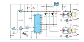
push button relay selector
This circuit was designed for use in a hi-fi showroom, where a choice of speakers could be connected to a stereo amplifier for comparative purposes.
The circuit serves as a speaker selector that facilitates the connection of multiple speakers to a...

bypass which improves the ability to resist surging of relay contact
During the power-up of the apparatus, the capacitor is primarily responsible for the emergence of surge current. The schematic diagram of the principle is illustrated in Fig. 1. After K1 closes, the capacitor begins to charge, assuming that the direct...
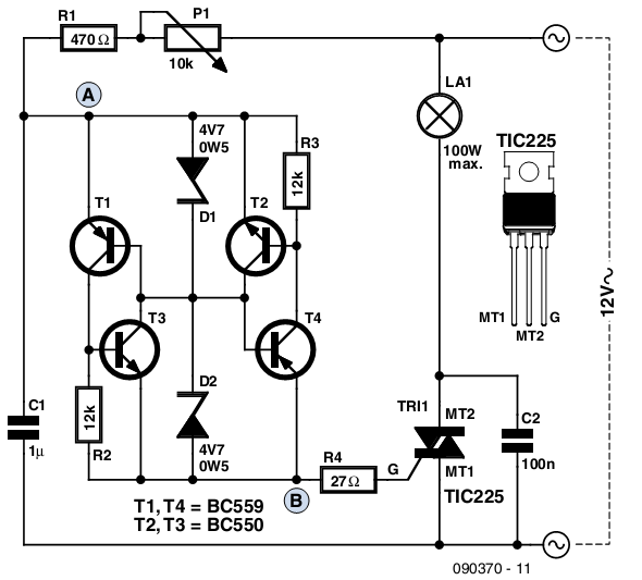
12 v ac dimmer
The circuit presented is based on a conventional design for a simple lamp dimmer, featuring a diac connected between points A and B. Unlike standard diac circuits that require a trigger voltage of 30 to 40V, this design operates effectively...

Dimmer Switch
Dimmer Switch - Dimmer Switch Working, Installation, Circuits and Explanation.
A dimmer switch is a device that allows for the adjustment of the brightness of a light fixture. It operates by varying the voltage and current supplied to the light source,...

Relay Coil Energy Saver
Some relays may become warm if they remain energized for an extended period. The circuit presented here will actuate the relay as before but will reduce the hold current through the relay coil by approximately 50%, significantly decreasing heat dissipation...

A linear dimming controller
An AC voltage of 30V is rectified. The positive terminal is connected to a fuse and a 100W bulb, while the negative terminal is connected to a thyristor. A Zener diode provides a stable bias voltage. A variable resistor (VR)...

DC relay circuits to delay the release of a second
The circuit depicted in Figure 6-24 includes a relay coil with both ends connected in parallel to either a resistor Rf or an auxiliary diode VD. This configuration is equivalent to providing power after a short circuit, which increases the...
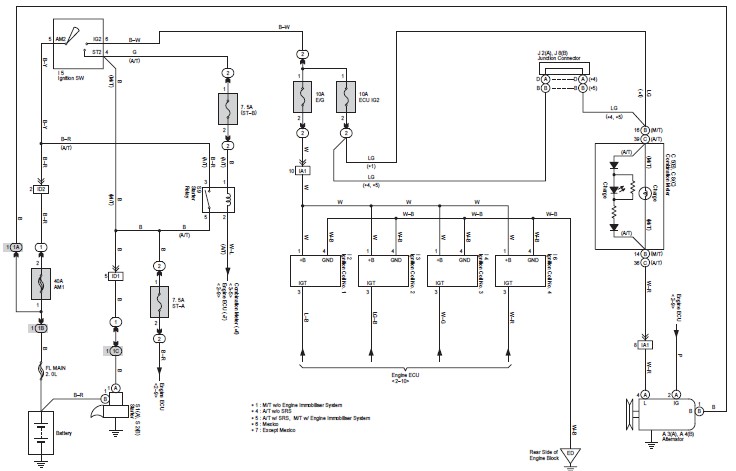
Toyota Avanza Wiring Diagram
This document contains the complete wiring diagram for the Toyota Avanza. It is highly useful for technicians and car owners during service or maintenance activities. The wiring diagram includes the wiring for the Front Wiper and Washer, Headlight, ABS, and...