


High speed warning device
#warning device
#spark coil
#frequency to voltage
#engine rpm
#tachometer
#voltage comparator
#output transistor
#speed sensor

Description: A1 amplifies and regulates the signal from the spark coil. A2 converts frequency to voltage so that its output is a voltage proportional to engine RPM. A3 compares the tachometer voltage with the reference voltage and turns on the output transistor at the set speed. Amplifier A4 is used to generate an audible tone whenever the set speed is exceeded.
The circuit consists of several key components that work together to monitor and regulate engine speed. The first component, A1, functions as an amplifier and regulator, enhancing the signal received from the spark coil. This is crucial for ensuring that the subsequent components receive a stable and strong signal, which is necessary for accurate processing.
Following A1, A2 operates as a frequency-to-voltage converter. It takes the frequency signal derived from the engine's RPM and converts it into a corresponding voltage level. This output voltage is directly proportional to the engine's RPM, allowing for easy measurement and comparison in the next stage of the circuit.
A3 serves as a comparator. It compares the voltage output from A2 with a predetermined reference voltage. When the engine RPM reaches a specific threshold, A3 activates an output transistor. This action can trigger various responses in the system, such as activating a warning light or engaging a control mechanism, depending on the overall design of the circuit.
Additionally, A4 is employed to generate an audible tone when the engine exceeds the set speed. This amplifier is designed to produce a sound signal that alerts the operator of the engine's over-speed condition, enhancing safety and operational awareness.
Overall, the described circuit provides a comprehensive solution for monitoring engine RPM, ensuring that the engine operates within safe limits while providing audible alerts for over-speed conditions. Each component plays a vital role in the system, contributing to its overall functionality and reliability.A1 amplifies and regulates the signal from the spark coil. A2 converts frequency to voltage so that its output is a voltage proportional to engine rpm. A3 compares the tachometer voltage with the reference voltage and turns on the output transistor at the set speed Amplifier A4 is used to generate an audible tone whenever the set speed is exceeded.
The circuit consists of several key components that work together to monitor and regulate engine speed. The first component, A1, functions as an amplifier and regulator, enhancing the signal received from the spark coil. This is crucial for ensuring that the subsequent components receive a stable and strong signal, which is necessary for accurate processing.
Following A1, A2 operates as a frequency-to-voltage converter. It takes the frequency signal derived from the engine's RPM and converts it into a corresponding voltage level. This output voltage is directly proportional to the engine's RPM, allowing for easy measurement and comparison in the next stage of the circuit.
A3 serves as a comparator. It compares the voltage output from A2 with a predetermined reference voltage. When the engine RPM reaches a specific threshold, A3 activates an output transistor. This action can trigger various responses in the system, such as activating a warning light or engaging a control mechanism, depending on the overall design of the circuit.
Additionally, A4 is employed to generate an audible tone when the engine exceeds the set speed. This amplifier is designed to produce a sound signal that alerts the operator of the engine's over-speed condition, enhancing safety and operational awareness.
Overall, the described circuit provides a comprehensive solution for monitoring engine RPM, ensuring that the engine operates within safe limits while providing audible alerts for over-speed conditions. Each component plays a vital role in the system, contributing to its overall functionality and reliability.A1 amplifies and regulates the signal from the spark coil. A2 converts frequency to voltage so that its output is a voltage proportional to engine rpm. A3 compares the tachometer voltage with the reference voltage and turns on the output transistor at the set speed Amplifier A4 is used to generate an audible tone whenever the set speed is exceeded.

Digital Bike Tachometer Circuit
This digital DIY tachometer for bicycles utilizes two reed switches to gather speed information. The reed switches are positioned near the wheel rim, where permanent magnets are mounted on the wheel spokes. As the spokes rotate, the magnets pass by...

Early VDO Tachometer Guts
The "crossed-flags" topology of a monostable multivibrator is utilized in a 912 tachometer circuit. Resistor R5, which sets the discharge rate of capacitor C2, differs from that used in a 911 tachometer. The 912 configuration operates at a 50% duty...

Contactless Tachometer
The tachometer, also known as a revolution counter, is an instrument that measures the speed of rotating machinery, typically expressed in revolutions per minute (RPM). This project involves creating a custom sensor using a light-emitting diode (LED) as a light...
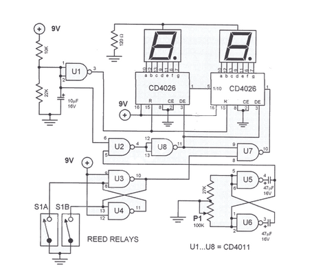
Digital Bike Tachometer
This digital DIY tachometer for bicycles utilizes two reed switches to obtain speed information. The reed switches are positioned near the rim of the wheel.
The digital DIY tachometer circuit is designed to provide accurate speed measurements for bicycles by leveraging...

Tachometer feedback control
The system employs the H21A1 optocoupler and a chopper disc to achieve enhanced speed regulation. This is effective when the dynamic characteristics of both the motor system and the feedback system are appropriately matched, ensuring stability. The tachometer feedback system...

Build A Digital Tachometer/RPM Counter Circuit
The circuit for the Digital Tachometer/RPM Counter consists of a few components. They should be connected according to the provided circuit diagram. The PIC used is on a demonstration board, meaning the clock, power, and ground pins are already connected,...

DIGITAL TACHOMETER COUNTER
This circuit generates a readout for a digital tachometer. IC9 functions as a 3-digit LED display driver, counter, and latch. IC8 operates the common cathode LEDs, which are activated by transistors Q1, Q2, and Q3. Refer to page 268, Fig....

Low-frequency-tachometer
This tachometer allows for the measurement of heartbeats, respiratory rates, and other low-frequency events that occur at intervals ranging from 0.33 to 40.96 seconds. The circuit detects the frequency, calculates the corresponding pulses per minute, and updates the LCD display...

Line-voltage-monitor
This circuit utilizes a type 741 operational amplifier (op amp) configured as a voltage comparator. One input of the 741 is connected to a reference voltage, sourced from a 12-V battery, via a resistor voltage divider. The voltage at the...