


I have a 315bl excavator. Engine intermittently shut off on
#excavator
#engine shutdown
#electrical circuit
#ignition system
#relay
#fuse box
#power circuit
#battery
#switch
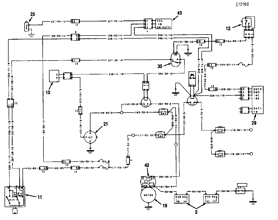
Description: A 315BL excavator experiences intermittent engine shutdowns, which can restart without issue. Currently, the engine does not turn off when the key is off, a daily occurrence. Air intake must sometimes be choked to shut down the engine, which usually restarts and then shuts off. Key components include: (1) Disconnect switch, (2) Batteries, (3) Power circuit, (4) Breaker 1, (5) Main relay, (6) Fuse box, (7) Low current circuit, (9) Cigar lighter, (10) Starter control relay, (11) Starter switch, (12) Neutral start switch, (13) Cab heater, (14) Air conditioner, (15) Lights, (16) Windshield wiper, (17) Windshield washer, (18) Start/stop circuit, (19) Starter motor, (20) Starter relay, (21) Alternator, (22) Horn, (23) Controller, (24) Switch panel, (25) Shut down solenoid, (26) Heater control unit, (27) Glow plug, (28) Charging circuit, (29) Timer relay, (30) Neutral start relay, (31) Battery breaker, (32) Breaker 2, (33) Breaker 3, (34) Fan relay, (35) Shut down timer, (36) Heater relay. The power circuit includes components such as battery (2), disconnect switch (1), battery breaker (31), breaker 1 (4), breaker 2 (32), breaker 3 (33), and main relay (5) to supply power to electrical components. The engine start/stop circuit incorporates starter control relay (10), starter motor (19), starter relay (20), timer relay (29), starter switch (11), shut down solenoid (25), neutral start relay (30), neutral start switch (12), and shut down timer (35). Cold weather starting aids include glow plug (27), heater control unit (26), and heater relay (36). The low current circuit is activated via switch panel (24), controlling lights (15) and windshield wiper (16). When the starter switch (11) is ON with the hydraulic activation control lever in the LOCKED position, current flows through timer relay (29) and neutral start switch (12) to neutral start relay (30), energizing it for start operations. In the START position (40), current flows to starter relay (20), closing its contacts and allowing current flow to terminal S of starter solenoid (42). If the switch is ON with the lever UNLOCKED, the engine will not start. When current reaches the starter solenoid (42), it closes contacts allowing current from the battery (2) to the starter motor (19) to initiate engine start. The alternator (21) generates electricity once the engine starts, sending a signal from terminal P of starter control relay (10) to open terminal S of starter relay (20), stopping the starter motor (19) to prevent damage. When the starter switch is OFF (41), the shut down timer (43) powers the shut down solenoid (25) for six seconds, cutting off fuel supply and stopping the engine. After six seconds, the governor actuator opens the fuel rack to allow for a restart. If the starter switch is turned ON before the six seconds elapse, the governor opens the fuel rack immediately.
The electrical schematic for the 315BL excavator encompasses a variety of circuits designed to manage power distribution, engine starting, and auxiliary functions. The primary circuit begins at the battery, which provides the necessary voltage and current to the entire system. The disconnect switch allows for safe disconnection of the battery, preventing accidental short circuits during maintenance.
The power circuit includes multiple breakers to protect against overloads, ensuring that each component operates within its specified limits. The main relay acts as a control point for energizing various circuits, including those for starting the engine and powering auxiliary systems.
The engine start/stop circuit is crucial for operation, utilizing a combination of relays and switches to ensure that the engine can only be started under safe conditions. The neutral start switch prevents the engine from starting unless the transmission is in the neutral position, providing an additional layer of safety.
For cold weather operations, the starting aid circuit is designed to facilitate engine ignition by preheating the engine components, thereby reducing the risk of failure during low-temperature conditions.
The low current circuit activates various components such as lights and wipers, enhancing the operator's visibility and safety during operation. The switch panel serves as the user interface for controlling these components, allowing for easy access and operation.
Overall, the schematic integrates these elements into a cohesive system, ensuring reliable operation of the excavator while maintaining safety and performance standards. Each component's interaction is carefully designed to prevent faults and ensure the machine operates efficiently under varying conditions.A 315bl excavator. Engine intermittently shut off on its own, but will start back up without a problem. Now machine will not shut off when key is off, happens every day now. I sometimes have to choke off air intake to shut down. most of the time the engine will restart then shut off. (1) Disconnect switch. (2) Batteries. (3) Power circuit.(4) Breaker 1. (5) Main relay. (6) Fuse box. (7) Low current circuit. (9) Cigar lighter. (10) Starter control relay. (11) Starter switch. (12) Neutral start switch. (13) Cab heater. (14) Air conditioner. (15) Lights. (16) Windshield wiper. (17) Windshield washer. (18) Start/stop circuit. (19) Starter motor. (20) Starter relay. (21) Alternator. (22) Horn. (23) Controller. (24) Switch panel. (25) Shut down solenoid. (26) Heater control unit. (27) Glow plug. (28) Charging circuit. (29) Timer relay. (30) Neutral start relay. (31) Battery breaker. (32) Breaker 2. (33) Breaker 3. (34) Fan relay. (35) Shut down timer. (36) Heater relay. This circuit supplies power to electric components and includes battery (2), disconnect switch (1), battery breaker (31), breaker 1 (4), breaker 2 (32), breaker 3 (33) and main relay (5). This circuit starts/stops the engine and includes starter control relay (10), starter motor (19), starter relay (20), timer relay (29), starter switch (11), shut down solenoid (25), neutral start relay (30), neutral start switch (12) and shut down timer (35).
Some machines are equipped with starting aid for cold weather starting purposes. The start aid circuit consists of glow plug (27), heater control unit (26) and heater relay (36). This circuit distributes power to several low current components. By operating switch panel (24), this circuit puts on lights (15) installed at chassis, cab and boom. Also, this circuit controls continuous or intermittent operation of the windshield wiper (16). (2) Battery. (10) Starter control relay. (11) Starter switch. (12) Neutral start switch. (19) Starter motor. (20) Starter relay. (21) Alternator. (25) Shut down solenoid. (29) Timer relay. (30) Neutral start relay. (42) Starter solenoid. (43) Shut down timer. When starter switch (11) is placed in ON position (39) with the hydraulic activation control lever in LOCKED position, there is current flow through timer relay (29) and neutral start switch (12) to neutral start relay (30). The coil of neutral start relay (30) is energized to be ready for the start operation. When starter switch (11) is placed in START position (40), there is current flow through neutral start relay (30) to starter relay (20).
The starter relay contacts are closed and there is current flow to terminal S of starter solenoid (42) from starter relay. NOTE: If switch (11) is placed in the ON position with the hydraulic activation control lever in UNLOCKED position, no current flows to starter relay (20) and the engine will not start.
When current flows to terminals of starter solenoid (42), contacts are closed and strong current flows from (+) terminal of battery (2) to B terminal of starter solenoid (42), which rotates motor (19) to start the engine. Once the engine starts, alternator (21) begins to generate electricity. Current signal is sent from P terminal of starter control relay (10). Terminal S of starter control relay (10) opens to turn the coil of starter relay (20) OFF. Starter motor (19) stops its rotation, which prevents the motor from being damaged due to over rotation.
When the starter switch is placed in OFF position (41), shut timer timer (43) supplies power for a certain period. Shut down solenoid (25) starts to move and stops fuel supply to the engine for 6 seconds, which stops the engine.
After the 6 seconds is over, the governor actuator opens fuel rack to make restart possible. If starter switch (11) is placed in the ON position before the 6 seconds pass, the governor opens the fuel rack at that time. Check the linkage first, spray it
The electrical schematic for the 315BL excavator encompasses a variety of circuits designed to manage power distribution, engine starting, and auxiliary functions. The primary circuit begins at the battery, which provides the necessary voltage and current to the entire system. The disconnect switch allows for safe disconnection of the battery, preventing accidental short circuits during maintenance.
The power circuit includes multiple breakers to protect against overloads, ensuring that each component operates within its specified limits. The main relay acts as a control point for energizing various circuits, including those for starting the engine and powering auxiliary systems.
The engine start/stop circuit is crucial for operation, utilizing a combination of relays and switches to ensure that the engine can only be started under safe conditions. The neutral start switch prevents the engine from starting unless the transmission is in the neutral position, providing an additional layer of safety.
For cold weather operations, the starting aid circuit is designed to facilitate engine ignition by preheating the engine components, thereby reducing the risk of failure during low-temperature conditions.
The low current circuit activates various components such as lights and wipers, enhancing the operator's visibility and safety during operation. The switch panel serves as the user interface for controlling these components, allowing for easy access and operation.
Overall, the schematic integrates these elements into a cohesive system, ensuring reliable operation of the excavator while maintaining safety and performance standards. Each component's interaction is carefully designed to prevent faults and ensure the machine operates efficiently under varying conditions.A 315bl excavator. Engine intermittently shut off on its own, but will start back up without a problem. Now machine will not shut off when key is off, happens every day now. I sometimes have to choke off air intake to shut down. most of the time the engine will restart then shut off. (1) Disconnect switch. (2) Batteries. (3) Power circuit.(4) Breaker 1. (5) Main relay. (6) Fuse box. (7) Low current circuit. (9) Cigar lighter. (10) Starter control relay. (11) Starter switch. (12) Neutral start switch. (13) Cab heater. (14) Air conditioner. (15) Lights. (16) Windshield wiper. (17) Windshield washer. (18) Start/stop circuit. (19) Starter motor. (20) Starter relay. (21) Alternator. (22) Horn. (23) Controller. (24) Switch panel. (25) Shut down solenoid. (26) Heater control unit. (27) Glow plug. (28) Charging circuit. (29) Timer relay. (30) Neutral start relay. (31) Battery breaker. (32) Breaker 2. (33) Breaker 3. (34) Fan relay. (35) Shut down timer. (36) Heater relay. This circuit supplies power to electric components and includes battery (2), disconnect switch (1), battery breaker (31), breaker 1 (4), breaker 2 (32), breaker 3 (33) and main relay (5). This circuit starts/stops the engine and includes starter control relay (10), starter motor (19), starter relay (20), timer relay (29), starter switch (11), shut down solenoid (25), neutral start relay (30), neutral start switch (12) and shut down timer (35).
Some machines are equipped with starting aid for cold weather starting purposes. The start aid circuit consists of glow plug (27), heater control unit (26) and heater relay (36). This circuit distributes power to several low current components. By operating switch panel (24), this circuit puts on lights (15) installed at chassis, cab and boom. Also, this circuit controls continuous or intermittent operation of the windshield wiper (16). (2) Battery. (10) Starter control relay. (11) Starter switch. (12) Neutral start switch. (19) Starter motor. (20) Starter relay. (21) Alternator. (25) Shut down solenoid. (29) Timer relay. (30) Neutral start relay. (42) Starter solenoid. (43) Shut down timer. When starter switch (11) is placed in ON position (39) with the hydraulic activation control lever in LOCKED position, there is current flow through timer relay (29) and neutral start switch (12) to neutral start relay (30). The coil of neutral start relay (30) is energized to be ready for the start operation. When starter switch (11) is placed in START position (40), there is current flow through neutral start relay (30) to starter relay (20).
The starter relay contacts are closed and there is current flow to terminal S of starter solenoid (42) from starter relay. NOTE: If switch (11) is placed in the ON position with the hydraulic activation control lever in UNLOCKED position, no current flows to starter relay (20) and the engine will not start.
When current flows to terminals of starter solenoid (42), contacts are closed and strong current flows from (+) terminal of battery (2) to B terminal of starter solenoid (42), which rotates motor (19) to start the engine. Once the engine starts, alternator (21) begins to generate electricity. Current signal is sent from P terminal of starter control relay (10). Terminal S of starter control relay (10) opens to turn the coil of starter relay (20) OFF. Starter motor (19) stops its rotation, which prevents the motor from being damaged due to over rotation.
When the starter switch is placed in OFF position (41), shut timer timer (43) supplies power for a certain period. Shut down solenoid (25) starts to move and stops fuel supply to the engine for 6 seconds, which stops the engine.
After the 6 seconds is over, the governor actuator opens fuel rack to make restart possible. If starter switch (11) is placed in the ON position before the 6 seconds pass, the governor opens the fuel rack at that time. Check the linkage first, spray it

Cd Ignition System For Autos Circuit
At the core of the CD4-MX is an astable multivibrator, constructed using transistors Q1 and Q2, which drives step-up transformer T1. The output from T1 is rectified by diodes D3 to D6 and utilized to charge capacitor C4. Upon the...

Third batch start and stop cycle control circuits
The circuit illustrated in Figure 3-78 utilizes two relays for automatic control, featuring a more complex line structure. This configuration allows for intermittent motor operation. Additionally, it can operate continuously when switch SA is positioned to the right.
The circuit employs...
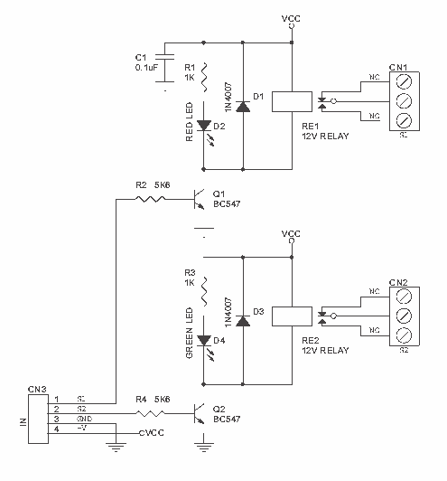
12V Relay Driver
Dual Channel Relay Board is a simple and convenient way to interface 2 relays for switching application in your project. Input - 12 VDC @ 84 mA. Output - two SPDT relay. Relay specification - 5 A @ 230 VAC....
Reducing Relay Power Consumption
This circuit demonstrates that microprocessors, personal computers, and the latest ultra-accurate digital-to-analog converters (DACs) are excessive for the task of sequentially controlling four relays.
The circuit utilizes a simple microcontroller or a basic timer IC to manage the operation of four...

Battery state of charge indicator circuit
During the charging process, the green light-emitting diode (LED) VLi indicates that the battery is sufficiently charged, while the red light-emitting diode (LED) VLz illuminates when the battery is low.
The circuit involves two light-emitting diodes (LEDs) serving as indicators for...

Battery Volt Meter
Battery Volt Meter Circuit Diagram. This circuit is designed to monitor the voltage level in Lead Acid or Tubular batteries. It provides four LED indicators to represent the voltage levels ranging from 9 volts to 14 volts.
The battery voltmeter circuit...

Pulsing Relay
A new member has joined the forum seeking assistance with a project involving the control of a CPU fan using a relay that is triggered by a stretch sensor. The circuit is currently set up, but the stretch sensor is...

Battery-capacity-tester
The test circuit indicates the remaining capacity of a battery by measuring the duration, in seconds, that an LED remains illuminated after the test switch (S1) is activated. This circuit has demonstrated reliability in testing nickel-cadmium (NiCad), carbon, and alkaline...

R/C On/Off Motor Controller with Brake
A relay-based on/off controller on the other hand can be very efficient. A typical relay has a contact resistance of 3 milliOhm. At 20A, this translates to a voltage drop of 0.06 volts, with a power loss of 1.2W. The...