


Magneto Coil Points Headlamp Horn wiring diagram
#ignition coil
#spark plug
#engine cut out switch
#voltage jump
#ground
#contact breaker
#pistons
#headlamp
#horn
#wiring diagram

Description: Timed precisely with the pistons' pumping, this component works with the ignition coil to create the voltage jump that causes the spark in the spark plug. The engine cut-out switch serves as an emergency button; when pressed, it provides a route to ground, stopping the current flow through the contact breaker and the ignition coil, thereby ending the sparking mechanism. At a general level, the ignition system must generate a high-voltage spark several hundred times a second at exactly the right time in the engine cycle. Creating a spark across the gap in the spark plug requires approximately 10,000 volts. The system must be able to repeat this process several million times without maintenance and under various conditions. This system is referred to as the Energy Transfer Ignition System and consists of an alternator, ignition coil, points, points cam, capacitor, and spark plug. Unlike other systems that utilize a battery and require a rectifier to convert the AC current generated by the alternator to DC current, this system operates entirely on AC current. The alternator includes rotor and stator windings, with the rotor being a six-pole magnet that spins, generating current in the six stator windings through electromagnetic induction. The ignition coil functions as a step-up transformer, producing the high voltage necessary for the spark plug. The voltage generated by the alternator flows through the primary coil of the transformer.
The Energy Transfer Ignition System is designed to provide reliable and efficient ignition for internal combustion engines. Its architecture allows for high-frequency spark generation, essential for optimal engine performance. The ignition coil, acting as a step-up transformer, amplifies the low voltage from the alternator into the high voltage required for creating a spark across the spark plug gap. This transformation is critical since the spark plug needs around 10,000 volts to initiate combustion effectively.
The alternator's design, featuring a six-pole rotor, is integral to the system's operation. As the rotor spins, it induces an alternating current (AC) in the stator windings. This AC output is directly utilized by the ignition coil, eliminating the need for additional components such as batteries or rectifiers, which are common in conventional ignition systems. This direct use of AC current enhances the system's reliability and reduces maintenance requirements, allowing it to function effectively across a wide range of environmental conditions.
The engine cut-out switch serves as a crucial safety feature, providing an immediate means to halt the ignition process in emergency situations. By grounding the circuit when activated, it ensures that the ignition coil ceases to function, preventing the generation of sparks and potential hazards.
Overall, the Energy Transfer Ignition System exemplifies a sophisticated approach to engine ignition, combining efficiency with safety and reliability, making it suitable for various applications in automotive and industrial engines.Timed precisely with the pistons` pumping, this component works with the ignition coil to create the voltage jump that causes the spark in the spark plug. Engine Cut Out Switch - Essentially an emergency button, when pressed, this provides a route to ground so that current stops flowing through the contact breaker and the ignitio
n coil, ending the sparking mechanism. At a general level, the ignition system must generate a high voltage spark several hundred times a second at exactly the right time in the engine cycle. Creating a spark across the gap in the spark plug requires about 10, 000 volts. Our system must be able to repeat this several million times without maintenance and in a variety of conditions.
Our system is called an Energy Transfer Ignition System and consists of an alternator, ignition coil, points, points cam, capacitor, and spark plug. Where other systems use a battery and must then use a rectifier to covert the AC current generated by the alternator to DC current, our system operates entirely on AC current.
(More details about other systems below) The alternator consists of a rotor and stator windings. The rotor is a six-pole magnet which spins and, through electromagnetic induction, generates current in the six stator windings. The ignition coil is a step-up transformer which generates the high voltage necessary for the spark plug.
Voltage generated by the alternator flows through the primary coil of the transformer.
The Energy Transfer Ignition System is designed to provide reliable and efficient ignition for internal combustion engines. Its architecture allows for high-frequency spark generation, essential for optimal engine performance. The ignition coil, acting as a step-up transformer, amplifies the low voltage from the alternator into the high voltage required for creating a spark across the spark plug gap. This transformation is critical since the spark plug needs around 10,000 volts to initiate combustion effectively.
The alternator's design, featuring a six-pole rotor, is integral to the system's operation. As the rotor spins, it induces an alternating current (AC) in the stator windings. This AC output is directly utilized by the ignition coil, eliminating the need for additional components such as batteries or rectifiers, which are common in conventional ignition systems. This direct use of AC current enhances the system's reliability and reduces maintenance requirements, allowing it to function effectively across a wide range of environmental conditions.
The engine cut-out switch serves as a crucial safety feature, providing an immediate means to halt the ignition process in emergency situations. By grounding the circuit when activated, it ensures that the ignition coil ceases to function, preventing the generation of sparks and potential hazards.
Overall, the Energy Transfer Ignition System exemplifies a sophisticated approach to engine ignition, combining efficiency with safety and reliability, making it suitable for various applications in automotive and industrial engines.Timed precisely with the pistons` pumping, this component works with the ignition coil to create the voltage jump that causes the spark in the spark plug. Engine Cut Out Switch - Essentially an emergency button, when pressed, this provides a route to ground so that current stops flowing through the contact breaker and the ignitio
n coil, ending the sparking mechanism. At a general level, the ignition system must generate a high voltage spark several hundred times a second at exactly the right time in the engine cycle. Creating a spark across the gap in the spark plug requires about 10, 000 volts. Our system must be able to repeat this several million times without maintenance and in a variety of conditions.
Our system is called an Energy Transfer Ignition System and consists of an alternator, ignition coil, points, points cam, capacitor, and spark plug. Where other systems use a battery and must then use a rectifier to covert the AC current generated by the alternator to DC current, our system operates entirely on AC current.
(More details about other systems below) The alternator consists of a rotor and stator windings. The rotor is a six-pole magnet which spins and, through electromagnetic induction, generates current in the six stator windings. The ignition coil is a step-up transformer which generates the high voltage necessary for the spark plug.
Voltage generated by the alternator flows through the primary coil of the transformer.
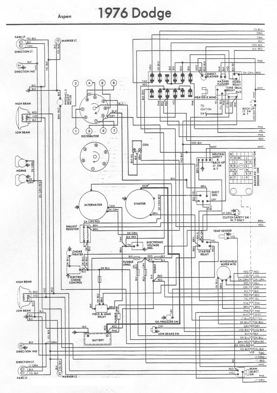
1976 dodge aspen wiring diagram
The Dodge Aspen was a compact car produced from 1976 to 1980 by Chrysler Corporation's Dodge division. The 1976 Aspen model year was available as a 2-door coupe, 4-door sedan, or 4-door station wagon, and it came in three trim...

CB125S WIRING DIAGRAM
CB125S Wiring Diagram Manual PDF Download.
The CB125S Wiring Diagram Manual provides a comprehensive guide for understanding the electrical system of the CB125S motorcycle. This manual includes detailed wiring diagrams that illustrate the connections between various electrical components, such as the...

1995 ford ranger wiring diagram
The part of the 1995 Ford Ranger wiring diagram includes components such as the transmission range sensor, electronic engine control, clutch pedal position switch jumper, speed control, automatic transmission, starter interrupt relay, relay box, starter motor during engine starting, starter...

Wiring Diagram and Electrical Circuit Troubleshooting Of 1997 Chevrolet Blazer
The following circuit illustrates the wiring diagram and electrical circuit troubleshooting for the 1997 Chevrolet Blazer. Features include a 4.3-liter Vortec V-6 engine, an AM-FM stereo radio with CD player, rear-wheel drive managed by a four-speed automatic transmission, air conditioning,...

Automotive Wiring Diagrams
The circuit diagram presented here pertains to the electrical wiring of the 1986 Ford Bronco and F-Series Pickup. It is essential to thoroughly read and understand the electrical wiring diagram before making any modifications to the wiring of these vehicles....

Yamaha Wiring System
The following image illustrates the Yamaha 175 Wiring Diagram (CT2 and CT3 model) and Electrical System Schematic. It provides detailed information regarding the interconnection and wiring between electrical components of the motorcycle, including the battery, ground, headlight, taillight, horn, rectifier,...

2000 Plymouth Breeze Dash Light Wiring Diagram
2000 Plymouth Breeze Dash Light Wiring Diagram.
The 2000 Plymouth Breeze dash light wiring diagram provides a detailed overview of the electrical connections and components associated with the vehicle's dashboard lighting system. This diagram serves as a crucial reference for technicians...
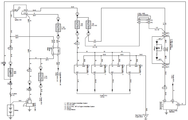
Toyota Avanza Wiring Diagram
This document contains the complete wiring diagram for the Toyota Avanza. It is highly useful for technicians and car owners during service or maintenance activities. The wiring diagram includes the wiring for the Front Wiper and Washer, Headlight, ABS, and...

Ignition Coil Wont Spark from Mosfet but DOES spark By Hand
An ignition coil is being used to generate sparks, controlled by a MOSFET powered by a 555 timer. The MOSFET is confirmed to be switching.
The circuit involves a 555 timer configured in astable mode to generate a pulse-width modulation (PWM)...