


NPN BJT in saturation base voltage irrelevant
#NPN BJT
#ignition coil
#logic line
#current-limiting resistor
#ground
#5V
#saturation
#base voltage
#transistor
#automotive

Description: Construct a simple circuit that pulls a logic line low each time an automotive ignition coil fires. The initial idea is to connect the negative terminal of the coil to the base of an NPN bipolar junction transistor (BJT) through a current-limiting resistor, with the emitter connected directly to ground. This setup would result in 5V on the collector and approximately 300V on the base resistor when triggered. There is a concern regarding the high voltage potentially affecting the circuit's operation. A voltage divider at the base might be a solution, though uncertainties remain about the overall functionality. The goal is to ensure that the transistor enters saturation when the ground is removed from the coil, causing the negative terminal to rise to around 300 volts. A switch (S1) in the schematic represents the IGBT or points triggering the ignition coil. There is a need for clarification on the proposed functionality, as passing the primary coil current through the base-emitter junction via a resistor may not work effectively. A schematic is requested to facilitate understanding, as the response to the design is complicated without visual representation. The BJT operates as a current-driven device, making base voltage irrelevant as long as it is within the device's ratings. However, the concern arises that when S1 opens, the primary current will be directed into the base of the transistor, which may exceed the required saturation current, potentially damaging the transistor. It is suggested to include a resistor from the base to ground, with a value likely around 100 ohms or less, depending on the primary coil current when S1 opens.
The proposed circuit involves utilizing an NPN BJT to detect the firing of an automotive ignition coil by pulling a logic line low. The ignition coil generates high voltage, and the circuit must be designed to handle this safely. The negative terminal of the ignition coil is connected to the base of the NPN transistor through a current-limiting resistor. This resistor is crucial as it protects the transistor from excessive base current when the coil fires. The emitter of the BJT is connected directly to ground, allowing the transistor to turn on when the base is pulled high.
To ensure proper operation, the circuit must account for the high voltage generated by the ignition coil. When the ignition coil fires, the negative terminal can reach voltages around 300V due to the counter-electromotive force (counter-EMF). This high voltage can cause issues if not managed correctly. A voltage divider could be implemented at the base to ensure that the base-emitter voltage remains within safe limits, allowing the transistor to operate effectively without damage.
In addition to the base resistor, it is advisable to include a resistor from the base to ground. This resistor serves to limit the base current and ensures that the transistor does not enter saturation prematurely, which could happen if the primary current from the coil is too high. The suggested value of around 100 ohms or less is a starting point, allowing for adjustments based on the specific characteristics of the ignition coil and the BJT used.
The switch (S1) in the schematic represents the mechanism that triggers the ignition coil. When S1 opens, the primary current from the coil will attempt to flow into the base of the transistor. Since the BJT is a current-driven device, it requires minimal base current (typically 1-2 mA) to saturate, while the primary current may be significantly higher, potentially leading to damage if not limited. The design needs to ensure that the base current is controlled, allowing the circuit to function as intended without compromising the integrity of the BJT.
In conclusion, careful consideration of component values and circuit design is essential to create a reliable circuit that effectively pulls a logic line low when the ignition coil fires. Properly managing the high voltage and current levels will ensure the circuit operates safely and effectively.Build as simple a circuit as possible that will pull a logic line low every time an automotive ignition coil `fires`. My first inclination is to simply attach the `negative` terminal of the coil to the base of of an NPN BJT through a current-limiting resistor, with the emitter tied directly to ground.
So there would be 5V on the coll ector and roughly 300V on the base resistor when being triggered. Somehow, though, I feel like I`m missing something fundamental that won`t let this work. Perhaps it`s just me being spooked by the `high` voltage. I suppose I could use a voltage divider at the base, but I still feel like I`m missing something. Looking for confirmation regarding the proposed functionality, or of my idiocy. Thanks. Edit: I don`t intend to pass any current through the transistor, besides what little is required by the device itself. The idea is that the transistor will go into saturation when the ground is removed from the coil (when the counter-EMF brings the coil`s `negative` terminal up to around 300 volts).
Here`s a (rather amateurish) schematic of what I`m thinking: Switch `S1` in that schematic is just a placeholder for the IGBT/Points triggering the ignition coil. Sorry again for the confusion, and thank you, everyone, for all the replies! Your description sounds like you are trying to pass the primary coil current through the base-emitter junction via a resistor that would severely limit the primary current and would not work.
Please post a circuit diagram. JIm Dearden May 22 `13 at 6:28 A BJT is in essence a current driven device, hence base voltage is, for most purposes, irrelevant, as long as the actual voltage expressed on the base-emitter junction is within device ratings. However, without a schematic, determining whether the approach is feasible or practical, is very difficult.
Please upload a schematic on any public image hosting site, and provide the link as an edit to the question: Someone with edit permissions will incorporate the diagram into your question. Anindo Ghosh May 22 `13 at 7:22 I didn`t see the schematic when I wrote my response. What you have depicted looks like it ought to work, but consider that when S1 opens, whatever the primary current happens to be, that will all be driven into the base of the transistor.
The transistor probably won`t need more than 1 or 2 mA to saturate, and for any decent output from the coil, the primary current is likely up in the hundreds of mA, maybe even an amp or more. This will be hard on the transistor. Suggest adding a resistor from base to ground. JustJeff May 24 `13 at 10:12 The value depends on the primary coil current at S1 opening and the transistor, but I`d guess it would be 100 ohms or less.
Assuming this is a one-off experiment, you could start low and work upward. JustJeff May 24 `13 at 10:15
The proposed circuit involves utilizing an NPN BJT to detect the firing of an automotive ignition coil by pulling a logic line low. The ignition coil generates high voltage, and the circuit must be designed to handle this safely. The negative terminal of the ignition coil is connected to the base of the NPN transistor through a current-limiting resistor. This resistor is crucial as it protects the transistor from excessive base current when the coil fires. The emitter of the BJT is connected directly to ground, allowing the transistor to turn on when the base is pulled high.
To ensure proper operation, the circuit must account for the high voltage generated by the ignition coil. When the ignition coil fires, the negative terminal can reach voltages around 300V due to the counter-electromotive force (counter-EMF). This high voltage can cause issues if not managed correctly. A voltage divider could be implemented at the base to ensure that the base-emitter voltage remains within safe limits, allowing the transistor to operate effectively without damage.
In addition to the base resistor, it is advisable to include a resistor from the base to ground. This resistor serves to limit the base current and ensures that the transistor does not enter saturation prematurely, which could happen if the primary current from the coil is too high. The suggested value of around 100 ohms or less is a starting point, allowing for adjustments based on the specific characteristics of the ignition coil and the BJT used.
The switch (S1) in the schematic represents the mechanism that triggers the ignition coil. When S1 opens, the primary current from the coil will attempt to flow into the base of the transistor. Since the BJT is a current-driven device, it requires minimal base current (typically 1-2 mA) to saturate, while the primary current may be significantly higher, potentially leading to damage if not limited. The design needs to ensure that the base current is controlled, allowing the circuit to function as intended without compromising the integrity of the BJT.
In conclusion, careful consideration of component values and circuit design is essential to create a reliable circuit that effectively pulls a logic line low when the ignition coil fires. Properly managing the high voltage and current levels will ensure the circuit operates safely and effectively.Build as simple a circuit as possible that will pull a logic line low every time an automotive ignition coil `fires`. My first inclination is to simply attach the `negative` terminal of the coil to the base of of an NPN BJT through a current-limiting resistor, with the emitter tied directly to ground.
So there would be 5V on the coll ector and roughly 300V on the base resistor when being triggered. Somehow, though, I feel like I`m missing something fundamental that won`t let this work. Perhaps it`s just me being spooked by the `high` voltage. I suppose I could use a voltage divider at the base, but I still feel like I`m missing something. Looking for confirmation regarding the proposed functionality, or of my idiocy. Thanks. Edit: I don`t intend to pass any current through the transistor, besides what little is required by the device itself. The idea is that the transistor will go into saturation when the ground is removed from the coil (when the counter-EMF brings the coil`s `negative` terminal up to around 300 volts).
Here`s a (rather amateurish) schematic of what I`m thinking: Switch `S1` in that schematic is just a placeholder for the IGBT/Points triggering the ignition coil. Sorry again for the confusion, and thank you, everyone, for all the replies! Your description sounds like you are trying to pass the primary coil current through the base-emitter junction via a resistor that would severely limit the primary current and would not work.
Please post a circuit diagram. JIm Dearden May 22 `13 at 6:28 A BJT is in essence a current driven device, hence base voltage is, for most purposes, irrelevant, as long as the actual voltage expressed on the base-emitter junction is within device ratings. However, without a schematic, determining whether the approach is feasible or practical, is very difficult.
Please upload a schematic on any public image hosting site, and provide the link as an edit to the question: Someone with edit permissions will incorporate the diagram into your question. Anindo Ghosh May 22 `13 at 7:22 I didn`t see the schematic when I wrote my response. What you have depicted looks like it ought to work, but consider that when S1 opens, whatever the primary current happens to be, that will all be driven into the base of the transistor.
The transistor probably won`t need more than 1 or 2 mA to saturate, and for any decent output from the coil, the primary current is likely up in the hundreds of mA, maybe even an amp or more. This will be hard on the transistor. Suggest adding a resistor from base to ground. JustJeff May 24 `13 at 10:12 The value depends on the primary coil current at S1 opening and the transistor, but I`d guess it would be 100 ohms or less.
Assuming this is a one-off experiment, you could start low and work upward. JustJeff May 24 `13 at 10:15

half bridge ignition coil driver
Ignition coil drivers that utilize an oscillator chip like the NE555 and a single switching device are a common beginner high voltage project. This version highlights some of the most important issues associated with this approach. Firstly, a desire for...

Motor time division control circuit composed of transistor and NE555
Figure 2-32 (a) illustrates the time control diagram for a motor operated by switch S1. When S1 is set to position 1, the power driver circuit supplies current to the motor, enabling it to run. When S1 is switched to...

Six a start and stop intermittent cycle control circuits
The circuit illustrated in Figure 3-81 employs a transistor delay circuit to facilitate start-stop cycle control. It can operate in both manual and automatic modes. The circuit is primarily governed by the motor run time circuit, which includes transistors VTi...

transistor as a switch circuit problems
A circuit is being designed that incorporates two key switches, which must both be closed for current to flow through the circuit.
The proposed circuit configuration employs two key switches connected in series. In this arrangement, the current can only pass...

4 transistor 500mw fm transmitter
The audio circuit described is a microphone utilizing two 2N3904 transistors as the audio preamplifier. The audio/microphone gain is adjustable via a 5k preset potentiometer. The circuit employs a Colpitts oscillator for frequency generation, which is free-running and operates at...

Wilf Rigter`s SIMD1 V2
In the never-ending quest for simplicity, even one extra diode is a price I loathe to pay. To avoid using extra components, it struck me that the two diodes in SIMD1 V1 were connected like the two junctions in one...

DIY Homemade Ignition Coil Driver
One of the simplest methods to create a battery-powered high-voltage power supply is by utilizing a common car ignition coil. Ignition coils function as a type of induction transformer, inspired by the Tesla Coil invented by Nikola Tesla in 1891....

Simple preamplifier circuits by transistors
When there is a need to amplify audio signals from various sources before they reach a custom amplifier, a preamplifier (or preamp) is typically employed. This document suggests a specific circuit that is interesting due to its use of a...
rising pitch siren
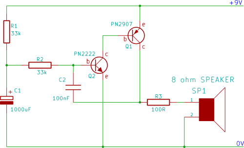
A two-transistor electronic siren breadboard circuit that produces an audible rising pitch on a loudspeaker. This circuit serves as a tutorial for beginners in electronics.
The two-transistor siren circuit operates by utilizing the properties of transistors to create an oscillating signal...