


Rear Fog Light Controller With Delay
#fog light
#delay
#controller
#automotive
#lighting
#driver safety
#circuit design
#vehicle electronics

Description: It is assumed that most readers are considerate drivers who do not activate their rear fog lights when closely followed by other vehicles. Following drivers may mistakenly think that the vehicle is braking, leading them to react by applying their brakes, which could create a dangerous situation. To prevent such potentially hazardous incidents, a rear fog light delay circuit is proposed. Switch S1 serves as the on/off control for rear fog lights L1 and L2. When this switch is closed, the gate-source voltage (Vgs) of MOSFET T1 becomes increasingly negative, causing the integrated circuit (IC) to conduct more vigorously. This results in the lights gradually increasing in brightness, reaching maximum intensity after a delay of approximately 20 seconds, determined by the time constant R2/C1. The gate of T1 can be adjusted using preset PI, which compensates for the initial period when the lights are switched on but not yet illuminated, as they require hundreds of milliamperes to light up. With PI properly set, the lamps will illuminate dimly as soon as the control switch is closed. The gate potential will match the voltage at the wiper of PI, noting that C1 is still discharged at that time. Although T1 experiences maximum dissipation during the transitional phase (from switch-on to full lamp brightness), the heatsink required is calculated based on the dissipation when the lamps are fully illuminated.
The rear fog light delay circuit is designed to enhance road safety by preventing abrupt reactions from following drivers. The circuit operates through a combination of a MOSFET and passive components, which control the gradual illumination of the fog lights. The switch S1 acts as the primary control element, allowing the driver to activate the fog lights when needed.
Upon activation, the MOSFET T1 begins to conduct, and the gate-source voltage (Vgs) is crucial for controlling the rate at which the lights brighten. The time constant, determined by the resistor R2 and capacitor C1, plays a significant role in establishing the delay period. This delay allows the driver to switch on the fog lights without immediately blinding the drivers behind, which could lead to confusion or accidents.
The preset PI is an essential feature of the circuit, as it provides initial bias to the MOSFET, ensuring that the fog lights can illuminate weakly before achieving full brightness. This design consideration enhances the circuit's effectiveness by allowing for a smoother transition in light intensity, thereby minimizing the risk of misinterpretation by following vehicles.
In terms of thermal management, the dissipative characteristics of the MOSFET T1 during the transitional phase must be carefully evaluated. The heatsink should be designed based on the maximum dissipation during full lamp operation, ensuring that the component remains within safe operating temperatures even under prolonged use.
Overall, this rear fog light delay circuit not only improves visibility in adverse weather conditions but also contributes significantly to overall traffic safety by mitigating the risk of sudden braking reactions from trailing vehicles. We assume that most of our readers are thoughtful drivers who do not switch on their rear fog lights w hen closely followed by other traffic. Following drivers (for an instant) will think that you are braking (although they have seen no reason for your doing so) and thus slam on their brakes as well. This could cause a very dangerous situation. Avoid a potentially dangerous action and install the rear fog light delay circuit, presented here. Switch Si is the on/off control for rear fog lights LI and L2. As soon as this switch is closed, the gate-source voltage (Vgs) of MOSFET T1 will become more and more negative.
Thus, the IC will conduct harder and harder. This in turn causes the brightness of the lights to gradually become brighter. Maximum brightness is reached after a delay of about 20 seconds, which is determined by time constant R2/C1. The gate of T1 can be given a bias by preset PI. This provides compensation for the initial period after the lights are switched on and the lamps do not light, because they need hundreds of milliamperes before they can do so.
With PI set correctly, the lamps will light, albeit weakly, and immediately the control switch is closed. The gate potential is then equal to the voltage at the wiper of PI (remember that CI is then still discharged).
Although the dissipation of T1 is a maximum during the transitional period (between switch on and the lamps lighting brightly), the heatsink required is calculated on the basis of the dissipation when the lamps light brightly.
The rear fog light delay circuit is designed to enhance road safety by preventing abrupt reactions from following drivers. The circuit operates through a combination of a MOSFET and passive components, which control the gradual illumination of the fog lights. The switch S1 acts as the primary control element, allowing the driver to activate the fog lights when needed.
Upon activation, the MOSFET T1 begins to conduct, and the gate-source voltage (Vgs) is crucial for controlling the rate at which the lights brighten. The time constant, determined by the resistor R2 and capacitor C1, plays a significant role in establishing the delay period. This delay allows the driver to switch on the fog lights without immediately blinding the drivers behind, which could lead to confusion or accidents.
The preset PI is an essential feature of the circuit, as it provides initial bias to the MOSFET, ensuring that the fog lights can illuminate weakly before achieving full brightness. This design consideration enhances the circuit's effectiveness by allowing for a smoother transition in light intensity, thereby minimizing the risk of misinterpretation by following vehicles.
In terms of thermal management, the dissipative characteristics of the MOSFET T1 during the transitional phase must be carefully evaluated. The heatsink should be designed based on the maximum dissipation during full lamp operation, ensuring that the component remains within safe operating temperatures even under prolonged use.
Overall, this rear fog light delay circuit not only improves visibility in adverse weather conditions but also contributes significantly to overall traffic safety by mitigating the risk of sudden braking reactions from trailing vehicles. We assume that most of our readers are thoughtful drivers who do not switch on their rear fog lights w hen closely followed by other traffic. Following drivers (for an instant) will think that you are braking (although they have seen no reason for your doing so) and thus slam on their brakes as well. This could cause a very dangerous situation. Avoid a potentially dangerous action and install the rear fog light delay circuit, presented here. Switch Si is the on/off control for rear fog lights LI and L2. As soon as this switch is closed, the gate-source voltage (Vgs) of MOSFET T1 will become more and more negative.
Thus, the IC will conduct harder and harder. This in turn causes the brightness of the lights to gradually become brighter. Maximum brightness is reached after a delay of about 20 seconds, which is determined by time constant R2/C1. The gate of T1 can be given a bias by preset PI. This provides compensation for the initial period after the lights are switched on and the lamps do not light, because they need hundreds of milliamperes before they can do so.
With PI set correctly, the lamps will light, albeit weakly, and immediately the control switch is closed. The gate potential is then equal to the voltage at the wiper of PI (remember that CI is then still discharged).
Although the dissipation of T1 is a maximum during the transitional period (between switch on and the lamps lighting brightly), the heatsink required is calculated on the basis of the dissipation when the lamps light brightly.

simplest smf automotive battery charger
A simple battery charger circuit is described, utilizing a single transistor for voltage detection and automatically disconnecting the battery from the supply when fully charged. The circuit's high voltage trip point is set to switch off the charging voltage when...
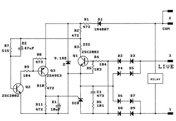
Delay Timer
Once the mains power supply is interrupted, the relay will only activate after a delay of 150 to 210 seconds, depending on the tolerance of the RC circuit.
The described circuit operates as a time delay relay system, which is crucial...

case stepper
Beige Bag Software has been offering affordable and innovative circuit design tools since 1990. B2 Spice provides schematics as well as analog, digital, and mixed-mode electronic circuit simulation. It integrates with EAGLE and CADSTAR PCB software.
B2 Spice is a powerful...

Delay switching for power amplifiers
This delay can be used in power amplifiers to prevent the fuses from failing when the amplifier is turned on. The circuit is very simple with a relay that is turned on when C2 and C3 are charged. If the...

Automobile Lights-On Reminder
The circuit provides a visible or audible warning when the headlights are on. It utilizes a 2N1305 transistor as a switch to activate either a Sonalert tone generator or a small 12-V lamp. The operating current for the transistor is...

Electronic Projects
This program includes circuit design CAD, simulation, and auto-routing PC layout. PSPICE is also utilized at Unisys, which offers more capabilities but costs six times as much and requires annual renewal. With these requirements and others in mind, a variation...
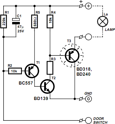
Vehicle Interior Lighting With Switch-Off Delay
Nowadays, a switch-off delay for vehicle interior lighting is a standard feature. However, certain models with minimal settings or older vehicles leave users in the dark as soon as they enter and close the door. This situation calls for an...
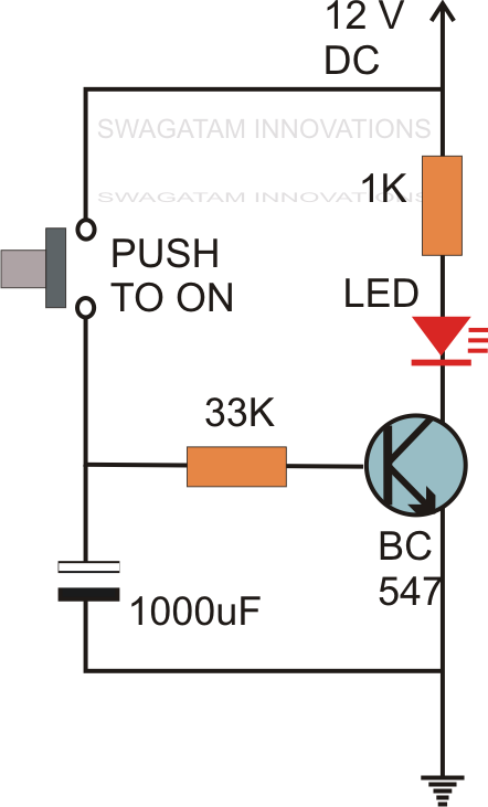
Simple Delay Timer Circuit
Without the specified delay, the circuit could malfunction or even sustain damage. A capacitor, which is a crucial component of the circuit, is positioned at the other end of the base resistor rather than directly connected to the base of...

controller
As summer approaches, many individuals focus on staying cool during hot days. For some, this means turning on the air conditioner and enjoying a cold beverage. However, it is essential to consider how to maintain the temperature of radio equipment...