


Vehicle lights at night rendezvous controlled circuit
#vehicle lights
#night driving
#traffic regulations
#light control
#automotive safety
#alternating lights
#headlight control
#driving circuits

Description: When driving at night and approaching another vehicle, traffic regulations dictate that the distance between the two vehicles should be maintained. This is achieved by alternately activating and deactivating the high beams, while utilizing either the wide lights or low beam lights to ensure the safety of passing vehicles. The circuit depicted in Figure 13-50 is designed to fulfill this function, with ELi and EL2 representing the high beams and SA functioning as a manual switch.
The circuit in Figure 13-50 operates by controlling the high beam lights (ELi and EL2) in response to the manual switch (SA). When the switch is activated, it sends a signal to the circuit that alternates the power supply to the high beams. This alternation is crucial for maintaining compliance with traffic regulations, which require that drivers do not dazzle oncoming vehicles with constant high beam usage.
The circuit may include additional components such as resistors to limit current flow, ensuring that the high beams operate within their specified voltage ratings. A relay could also be incorporated to handle the higher current required by the high beams, allowing the manual switch to control the relay instead of directly powering the lights.
Furthermore, the circuit can be designed with a timer or a microcontroller to automate the alternation process, enhancing convenience and ensuring compliance with regulations without requiring constant manual intervention. Safety features, such as diodes, may be included to prevent back EMF from damaging the circuit components when the relay is deactivated.
In summary, the described circuit effectively manages the operation of vehicle high beams in accordance with traffic regulations, enhancing safety during nighttime driving by ensuring that drivers can communicate their presence without compromising the visibility of other road users.Driving at night, when there is a vehicle rendezvous, according to traffic regulations prescribed distance should begin two vehicles alternately opening and closing the big lig ht, while OFF, showing the wide lights or low beam lights to ensure the safety of vehicles pass through. The circuit shown in Figure 13-50 to play this role. Figure, ELi and EL2 for the big lights, SA manual switch.
The circuit in Figure 13-50 operates by controlling the high beam lights (ELi and EL2) in response to the manual switch (SA). When the switch is activated, it sends a signal to the circuit that alternates the power supply to the high beams. This alternation is crucial for maintaining compliance with traffic regulations, which require that drivers do not dazzle oncoming vehicles with constant high beam usage.
The circuit may include additional components such as resistors to limit current flow, ensuring that the high beams operate within their specified voltage ratings. A relay could also be incorporated to handle the higher current required by the high beams, allowing the manual switch to control the relay instead of directly powering the lights.
Furthermore, the circuit can be designed with a timer or a microcontroller to automate the alternation process, enhancing convenience and ensuring compliance with regulations without requiring constant manual intervention. Safety features, such as diodes, may be included to prevent back EMF from damaging the circuit components when the relay is deactivated.
In summary, the described circuit effectively manages the operation of vehicle high beams in accordance with traffic regulations, enhancing safety during nighttime driving by ensuring that drivers can communicate their presence without compromising the visibility of other road users.Driving at night, when there is a vehicle rendezvous, according to traffic regulations prescribed distance should begin two vehicles alternately opening and closing the big lig ht, while OFF, showing the wide lights or low beam lights to ensure the safety of vehicles pass through. The circuit shown in Figure 13-50 to play this role. Figure, ELi and EL2 for the big lights, SA manual switch.
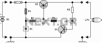
Motor Bike Headlight Controller Circuit
Motor Bike Headlight Controller Circuit. This circuit automatically turns a motorcycle's headlight on and off, independently of both the light and ignition switches, provided the battery is fully charged. The first stage...
The motorcycle headlight controller circuit is designed to enhance...

Light control relay control lamp
The circuit operates on 220V AC input, which is transformed to approximately 12V DC using a step-down transformer (T), a diode bridge rectifier (VDI-VD4), and a filter capacitor (C1). This setup is designed to power the entire circuit. The light...

860 Watt limited-range light control
The system is designed to regulate an 860-watt lamp load from half to full power. This is achieved through the controlled half-plus-fixed half-wave phase control method. Applying half power to an incandescent lamp results in 30% of the full light...

Automatic light control circuit curtains
The circuit operates as follows: each morning, light enters the silicon photocell, generating a force that causes transistor VT1 to conduct. As a result, capacitor C charges, leading to an increase in voltage. This rising voltage causes the emitter current...

Manual Headlight/Spotlight Control For Autos Circuit
Pressing the START pushbutton activates either the headlights or spotlights for a specified duration. After 1 minute, determined by R1 and C1, the lights will turn off as the NE555 timer completes its cycle.
The circuit utilizes a NE555 timer in...
Light control relay control lamp
The circuit operates on 220V AC input, which is transformed to approximately 12V DC using a step-down transformer (T), a diode bridge rectifier (VDI-VD4), and a filter capacitor (C1). This setup is designed to power the entire circuit. The light...

motor bike headlight controller circuit
This circuit automatically controls the headlight of a motorcycle, turning it on and off independently of the light and ignition switches, as long as the battery is fully charged. The initial stage employs a 220-ohm resistor and ZD1 to keep...

Put That Light Out
If the light in a seldom-used room, such as a loft, is forgotten and left on, it can remain illuminated for extended periods, leading to significant electricity costs. To address this issue, electronics enthusiasts can design a simple circuit to...
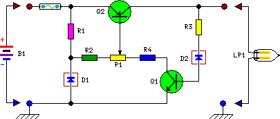
Motor Bike Headlight Controller Circuit
This circuit automatically activates and deactivates a motorcycle's headlight, functioning independently of both the light and ignition switches, as long as the battery is fully charged. The initial stage employs a 220-ohm resistor and ZD1 to keep transistor Q1 in...