


Windshield wiper control
#windshield wiper
#interval control
#automotive
#wiper motor
#timing circuit
#car electronics
#vehicle control
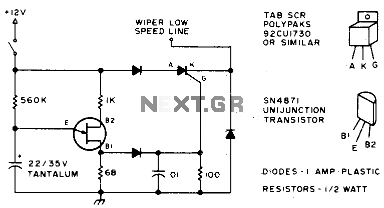
Description: Here is an effective method to configure windshield wipers using an interval circuit. This setup requires only two connections to the car's wiper control, in addition to a ground connection. Variable control can be achieved by replacing a 560 K resistor with a 500 K potentiometer in series with a 100 K fixed resistor.
The interval wiper circuit provides an efficient way to manage the operation of windshield wipers, allowing them to operate intermittently rather than continuously. The circuit typically involves a timer IC, such as the NE555, configured in astable mode to generate a pulse-width modulation signal. The two connections to the car's wiper control allow the circuit to interface directly with the existing wiper motor control system.
The ground connection is essential for establishing a common reference point for the circuit. The use of a potentiometer (500 K) in conjunction with a fixed resistor (100 K) enables the user to adjust the interval timing of the wipers. By varying the resistance, the timing can be tailored to suit different weather conditions or personal preferences.
In practical implementation, the circuit may include additional components such as diodes for protection against back EMF generated by the wiper motor, as well as capacitors to stabilize the power supply and filter out noise. The choice of components should be made with consideration of the specific vehicle's electrical characteristics to ensure compatibility and reliability.
Overall, this circuit design offers a straightforward solution for enhancing windshield wiper functionality, providing drivers with improved visibility during adverse weather conditions.Here"s a good way to set windshield wipers on an interval circuit. Only two connections to the car"s wiper control, plus ground, are required Variable control can be accomplished by substituting a 500 K pot in series with a 100 K fixed resistor in place of the 560 K.
The interval wiper circuit provides an efficient way to manage the operation of windshield wipers, allowing them to operate intermittently rather than continuously. The circuit typically involves a timer IC, such as the NE555, configured in astable mode to generate a pulse-width modulation signal. The two connections to the car's wiper control allow the circuit to interface directly with the existing wiper motor control system.
The ground connection is essential for establishing a common reference point for the circuit. The use of a potentiometer (500 K) in conjunction with a fixed resistor (100 K) enables the user to adjust the interval timing of the wipers. By varying the resistance, the timing can be tailored to suit different weather conditions or personal preferences.
In practical implementation, the circuit may include additional components such as diodes for protection against back EMF generated by the wiper motor, as well as capacitors to stabilize the power supply and filter out noise. The choice of components should be made with consideration of the specific vehicle's electrical characteristics to ensure compatibility and reliability.
Overall, this circuit design offers a straightforward solution for enhancing windshield wiper functionality, providing drivers with improved visibility during adverse weather conditions.Here"s a good way to set windshield wipers on an interval circuit. Only two connections to the car"s wiper control, plus ground, are required Variable control can be accomplished by substituting a 500 K pot in series with a 100 K fixed resistor in place of the 560 K.

Automobile Lights-On Reminder
The circuit provides a visible or audible warning when the headlights are on. It utilizes a 2N1305 transistor as a switch to activate either a Sonalert tone generator or a small 12-V lamp. The operating current for the transistor is...

simplest smf automotive battery charger
A simple battery charger circuit is described, utilizing a single transistor for voltage detection and automatically disconnecting the battery from the supply when fully charged. The circuit's high voltage trip point is set to switch off the charging voltage when...

1999 Pontiac Montana: console temperature MPG compass etc. failed
A 1999 Pontiac Montana has an information console that displays temperature, MPG, compass, and other data. This console experienced intermittent failures before completely ceasing to function. Concurrently, the radio display also malfunctioned, though the radio itself remained operational. The display...

Car battery charger Automative car and motorcycle schematics
The circuit is designed to operate with an external power supply, which is why it does not include a transformer, rectifier, or filter capacitors in the schematic. However, these components can be added if desired. To utilize the circuit, connect...

Automatic Windshield Washer Control
Most recent cars are equipped with a significant amount of electronics, including ABS brake systems, engine control with injection calculators, airbag activation, and various comfort functions. One such function, which is often overlooked due to its commonality, is the automatic...

freeze protector circuit
This is a simple freeze protector circuit diagram, also known as a timing circuit. It serves as a hobby project for beginners. This circuit can automatically operate any device after a fixed time once AC power supply is restored. The...

Camshaft Position Sensor
AutoZone Repair Guide for Engine Performance and Emission Control Components and Systems, specifically focusing on the Camshaft Position Sensor.
The Camshaft Position Sensor (CMP) is a critical component in modern internal combustion engines, playing a vital role in the management of...

weather car wont start and radio keyless entry power windows
When the weather is hot and the sun is shining, the car fails to start, and the radio, keyless entry, power windows, power locks, and power seats do not function. However, after sunset, everything operates normally. It is important to...

Automotive burglar alarm
The alarm activates after a 13-second delay and remains active for 1 to 1.5 minutes before automatically resetting. It can also be deactivated and reset by opening and reclosing switch SI.
The described circuit functions as a delay-triggered alarm system, incorporating...