


Windshield Wiper Interval Controller
#windshield wiper
#interval controller
#automotive
#timer
#delay circuit
#vehicle electronics
#compact design

Description: The windshield wiper interval circuit described here is compact and notable for utilizing two thyristors instead of a relay. It features only two connections and operates smoothly, even with multistage wiper circuits. The wire connecting the wiper motor to terminal 53 is severed, and new connections are established as illustrated in the diagram. When the interval switch (SI) is closed, capacitor (CI) charges through resistor (PI) and the wiper motor. After a predetermined time set by PI, transistor (T1) activates, triggering the thyristors. This action energizes the wiper motor through the thyristors and diode (D3), setting the wipers in motion. Simultaneously, CI discharges through diode (D2) and the thyristors. After a brief period, the wiper stop switch connects terminal 53 to the +12-V line, energizing the wiper motor through diode (D4). The thyristors turn off because the voltage drop across D3 and the thyristors exceeds that across D4. When the wipers reach the end of their travel, the stop switch connects terminal 53 to ground, allowing CI to recharge.
The windshield wiper interval circuit is designed to provide controlled operation of the wiper motor through a time-based interval system, enhancing the functionality of vehicle wipers. The circuit operates by utilizing two thyristors, which serve as electronic switches, replacing traditional mechanical relays. This design minimizes space requirements and improves reliability.
The operation begins with closing the interval switch (SI), which initiates the charging of capacitor (CI) through the resistor (PI) and the wiper motor. The time constant for the charging is determined by the values of PI and CI, allowing the user to set the desired interval for the wiper operation. Once the voltage across CI reaches a certain threshold, transistor (T1) is activated, which sends a triggering pulse to the thyristors, enabling them to conduct.
Upon the thyristors conducting, the wiper motor is powered through diode (D3), causing the wipers to start moving. During this motion, capacitor (CI) discharges through diode (D2) and the thyristors, providing the necessary current to maintain the operation of the wiper motor.
As the wipers complete their cycle, the wiper stop switch activates, connecting terminal 53 to the +12-V supply. This action energizes the wiper motor through diode (D4) while simultaneously causing the thyristors to turn off. The turn-off condition is achieved because the combined voltage drop across diode (D3) and the thyristors becomes greater than the voltage across diode (D4), effectively interrupting the current flow through the thyristors.
Once the wipers reach the end of their travel, the stop switch reconnects terminal 53 to ground, allowing capacitor (CI) to recharge, preparing the system for the next interval operation. This compact and efficient design ensures reliable wiper operation across various vehicle configurations, making it suitable for modern automotive applications. The windshield wiper interval circuit presented here is very compact and is noteworthy for its use of two thyristors, instead of a relay. It has only two connections and operates without any problems-even in conjunction with multistage wiper circuits. The connecting wire between the wiper motor and terminal 53 is cut and new connections are made (as shown in the diagram).
When the interval switch, SI, is closed, capacitor CI charges via PI and the wiper motor. After a time set with PI, transistor T1 switches on and triggers the thyristors. The wiper motor is then energized via the thyristors and D3 and sets the wipers into motion. At the same time, CI discharges via D2 and the thyristors. After a short time, the wiper stop switch connects terminal 53 to the +12-V line so that the wiper motor is energized via D4. The thyristors are switched off because the voltage drop across D3 plus Thl/Th2 is then greater than that across D4.
When the wipers reach the end of their travel again, the stop switch connects terminal 53 to ground and enables CI to charge again.
The windshield wiper interval circuit is designed to provide controlled operation of the wiper motor through a time-based interval system, enhancing the functionality of vehicle wipers. The circuit operates by utilizing two thyristors, which serve as electronic switches, replacing traditional mechanical relays. This design minimizes space requirements and improves reliability.
The operation begins with closing the interval switch (SI), which initiates the charging of capacitor (CI) through the resistor (PI) and the wiper motor. The time constant for the charging is determined by the values of PI and CI, allowing the user to set the desired interval for the wiper operation. Once the voltage across CI reaches a certain threshold, transistor (T1) is activated, which sends a triggering pulse to the thyristors, enabling them to conduct.
Upon the thyristors conducting, the wiper motor is powered through diode (D3), causing the wipers to start moving. During this motion, capacitor (CI) discharges through diode (D2) and the thyristors, providing the necessary current to maintain the operation of the wiper motor.
As the wipers complete their cycle, the wiper stop switch activates, connecting terminal 53 to the +12-V supply. This action energizes the wiper motor through diode (D4) while simultaneously causing the thyristors to turn off. The turn-off condition is achieved because the combined voltage drop across diode (D3) and the thyristors becomes greater than the voltage across diode (D4), effectively interrupting the current flow through the thyristors.
Once the wipers reach the end of their travel, the stop switch reconnects terminal 53 to ground, allowing capacitor (CI) to recharge, preparing the system for the next interval operation. This compact and efficient design ensures reliable wiper operation across various vehicle configurations, making it suitable for modern automotive applications. The windshield wiper interval circuit presented here is very compact and is noteworthy for its use of two thyristors, instead of a relay. It has only two connections and operates without any problems-even in conjunction with multistage wiper circuits. The connecting wire between the wiper motor and terminal 53 is cut and new connections are made (as shown in the diagram).
When the interval switch, SI, is closed, capacitor CI charges via PI and the wiper motor. After a time set with PI, transistor T1 switches on and triggers the thyristors. The wiper motor is then energized via the thyristors and D3 and sets the wipers into motion. At the same time, CI discharges via D2 and the thyristors. After a short time, the wiper stop switch connects terminal 53 to the +12-V line so that the wiper motor is energized via D4. The thyristors are switched off because the voltage drop across D3 plus Thl/Th2 is then greater than that across D4.
When the wipers reach the end of their travel again, the stop switch connects terminal 53 to ground and enables CI to charge again.

R/C Timer-Switch for Radio Control Applications
The project originated from a request by Tony Bowler, a member of the Long Eaton Club, who sought assistance in converting a "Golden Oldie" model to electric free-flight. He selected Vic Smeed's "Debutante" to be powered by seven AE size...

Delayed start for mains equipment
The schematic requires few components because the timer function has been incorporated by Nutchip. For once, from the start, made up of contacts of the relay RE1 connected to terminal M2. If we turn on an appliance at the end...

Simple timer
Press SI. The 100 µF electrolytic capacitor rapidly charges up from approximately 0 V. The transistor becomes forward biased, allowing collector current to flow and operate the relay. When SI is released, the capacitor discharges through the 33 K resistor...

Periodic Timer
A switched timer with equal make and equal space periods timing adjustable from over 6 minutes to 38 minutes. This timer circuit is similar to the 5 to 30 minute timer except that when switch S1 is closed, the on/off...

Repeating Timer No5
This circuit is a temperature-controlled version of Repeating Timer No. 3. The light-dependent resistor has been replaced by a temperature-dependent resistor, or thermistor. A small preset potentiometer allows the user to select the temperature threshold above which the timer will...
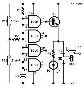
long delay timer schematics
This timer is designed to automatically switch off a portable radio after a set period, allowing users to relax without worrying about battery drain. Resistor R1 and capacitor C1 create a long time constant. When switch P2 is momentarily closed,...

Three Hour Timer
Manufacturers of cordless drills typically recommend a battery charging time of three hours. After this time, the battery should be disconnected from the charger to prevent the risk of overcharging. The following circuit is designed to prevent this scenario by...

Timer Circuit with optocoupler
A small circuit that can find a lot of applications for measuring time. It has the capability to inform with a sound signal from the BZ1. At the same time, there exists the possibility to drive an external circuit via...

A Tan Timer Circuit
This timer is designed for individuals seeking to achieve a tan while minimizing excessive exposure to sunlight. A rotary switch allows the user to set the timer based on six classified photo-types. A photoresistor adjusts the preset time value in...