


Wiper Speed Control
#wiper control
#variable speed
#car electronics
#automotive
#speed adjustment
#delay circuit
#vehicle accessories
#PWM control
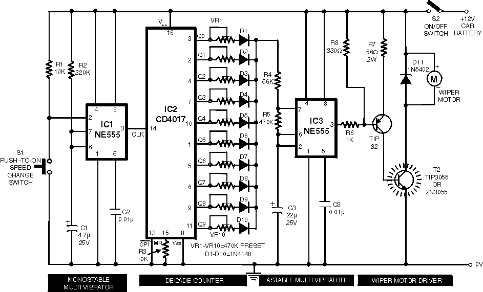
Description: Wiper Speed Control. A continuously operating wiper in a vehicle can be bothersome, particularly during light rain. The circuit described here allows for the adjustment of the wiper's sweeping rate, ranging from once per second to once every ten seconds.
The wiper speed control circuit typically employs a variable resistor or potentiometer to adjust the timing of the wiper motor operation. This circuit can be implemented using a simple timer IC, such as the NE555, configured in astable mode, to generate a square wave output that drives the wiper motor.
The key components of the circuit include the NE555 timer, a motor driver (such as a transistor or a relay), a potentiometer for speed adjustment, and capacitors for timing control. The potentiometer alters the resistance in the timing circuit, thereby changing the duty cycle of the output signal. This adjustment directly influences how often the wipers sweep across the windshield.
In the astable configuration, the NE555 timer continuously oscillates between its high and low states, which can be set to correspond to the desired wiper speed. The output from the NE555 can be fed into a transistor, which acts as a switch to control the wiper motor. The motor will then operate at the speed determined by the timing circuit, allowing the driver to set a comfortable wiper frequency based on the current weather conditions.
Additionally, diodes can be incorporated to protect the circuit from back EMF generated by the motor, ensuring the longevity and reliability of the wiper speed control system. This setup enhances the driving experience by providing customizable wiper functionality, adapting to varying levels of precipitation.Wiper Speed Control. A continuously working wiper in a car may prove to be a nuisance, especially when it is not raining heavily. By using the circuit described here one can vary sweeping rate of the wiper from once a second to once in ten seconds
The wiper speed control circuit typically employs a variable resistor or potentiometer to adjust the timing of the wiper motor operation. This circuit can be implemented using a simple timer IC, such as the NE555, configured in astable mode, to generate a square wave output that drives the wiper motor.
The key components of the circuit include the NE555 timer, a motor driver (such as a transistor or a relay), a potentiometer for speed adjustment, and capacitors for timing control. The potentiometer alters the resistance in the timing circuit, thereby changing the duty cycle of the output signal. This adjustment directly influences how often the wipers sweep across the windshield.
In the astable configuration, the NE555 timer continuously oscillates between its high and low states, which can be set to correspond to the desired wiper speed. The output from the NE555 can be fed into a transistor, which acts as a switch to control the wiper motor. The motor will then operate at the speed determined by the timing circuit, allowing the driver to set a comfortable wiper frequency based on the current weather conditions.
Additionally, diodes can be incorporated to protect the circuit from back EMF generated by the motor, ensuring the longevity and reliability of the wiper speed control system. This setup enhances the driving experience by providing customizable wiper functionality, adapting to varying levels of precipitation.Wiper Speed Control. A continuously working wiper in a car may prove to be a nuisance, especially when it is not raining heavily. By using the circuit described here one can vary sweeping rate of the wiper from once a second to once in ten seconds

Sound delay lamp circuit diagram
The telephone table lamp is designed to automatically illuminate during night ringing or when the phone is off-hook. After hanging up, the lamp will extinguish after a delay of 45 seconds. It is typically used as a general-purpose lamp with...

Conducting pipe control rechargeable delay circuit
The circuit features a delay action with an instantaneous reset control mechanism. It is categorized into three types: a conducting pipe rechargeable delay circuit, a tube cut-off control rechargeable delay circuit, and a discharge-type delay circuit. In the conducting pipe...

12v 10 minute Off-Delay timer
An Xbox 360 console previously experienced a problem known as the 3 Red Lights of Death (3RLOD). To address this issue, the stock heatsinks were removed, and a Koolance external water cooling system was installed. This modification has effectively resolved...

Circuit Delay and Speakers Protektor Using TL071
The circuit-delay relay for speakers serves as a delay mechanism that prevents the immediate activation of speakers when the amplifier is powered on. This feature is designed to protect the speakers from potential damage caused by sudden power surges. The...

Using music integrated circuit delay lamp
The circuit utilizes a KD-9300 music IC, which activates when the button switch (SB) is pressed, causing the electric lamp (E) to light up for approximately 20 seconds before automatically turning off. The setup includes a half-wave rectifier and a...

delay circuit for surround sound
This circuit utilizes the Mitsubishi M65830 Digital Delay chip, which has proven to be simple and effective for applications requiring a fixed delay. The serial data necessary for achieving various delay settings is not readily available and would significantly increase...
Conducting pipe control rechargeable delay circuit
The circuit features a delay action with an instantaneous reset control mechanism. It is categorized into three types: a conducting pipe rechargeable delay circuit, a tube cut-off control rechargeable delay circuit, and a discharge-type delay circuit. In the conducting pipe...
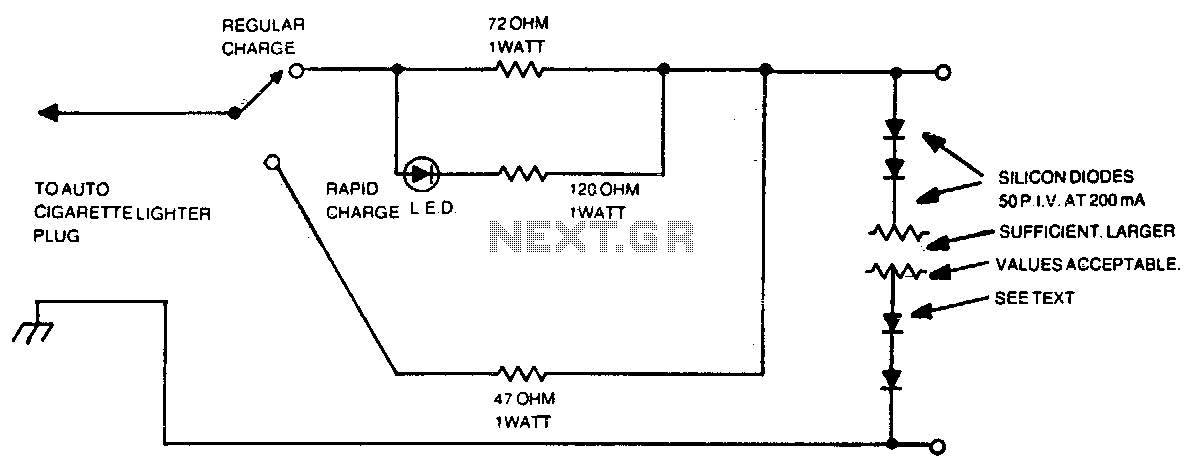
Automotive charger for ni-cad battery packs
The number of silicon diodes across the output is determined by the voltage of the battery pack. Each diode is considered at 0 volts. For example, a 10-volt pack would require 10/0 = 157, or 16 diodes.
In the context of...

Delay On Circuit
Protect your LCD or Plasma TV with this small delay-on circuit. The SMPS-based power supply of these modern electronic devices is susceptible to voltage spikes.
This delay-on circuit is designed to enhance the protection of LCD and Plasma TVs by mitigating...