


12v Battery Charger Circuit with Auto Cut off
#555 timer
#auto cut off
#DIY
#charge controller
#12v battery
#voltage comparator
#charging circuit
#preset voltage
#battery voltage
#simple schematic

Description: This is a simple DIY charge controller schematic created in response to a request from one of the readers on our Facebook page. The primary component of this automatic battery charger circuit is a 555 timer, which compares the voltage of the battery. It activates the charger if the battery voltage falls below a variable preset voltage (set to 12 volts in this case) and deactivates the charger when the voltage reaches 13.8 volts. The charging voltage can be adjusted by modifying the variable resistor. To comprehend the operation of this 12-volt battery charge controller circuit, familiarity with the internal diagram of the 555 timer is necessary. The pinout section at the bottom can provide additional information. There is also a charge controller utilizing an LM324 IC available, which includes a video demonstration. When the battery voltage exceeds 13.8 volts, the comparator output goes high, setting the flip-flop, which turns off the transistor and the relay. For an understanding of relay operation, refer to resources that explain how to connect relays, including animated demonstrations. If the battery voltage drops below the preset voltage, the lower comparator resets the flip-flop, turning on the transistor and activating the relay to charge the battery.
This DIY charge controller schematic employs a 555 timer IC configured in a comparator mode to manage the charging of a 12-volt lead-acid battery. The circuit operates by monitoring the battery voltage and controlling the charging process based on predefined voltage thresholds. The 555 timer has two comparators: one for the upper threshold (13.8 volts) and one for the lower threshold (12 volts).
When the battery voltage is below 12 volts, the output of the lower comparator remains low, allowing the flip-flop to reset. This condition activates the transistor, which in turn energizes the relay, connecting the charger to the battery. As the battery charges and the voltage rises, once it reaches 13.8 volts, the output of the upper comparator transitions high, setting the flip-flop. This action turns off the transistor, deactivating the relay and disconnecting the charger from the battery, thus preventing overcharging.
The variable resistor in the circuit allows for fine-tuning of the charging voltage, accommodating different battery chemistries and conditions. This flexibility is crucial for optimizing battery life and performance. The circuit's design also emphasizes safety and reliability, ensuring that the battery is charged efficiently while safeguarding against damage from overvoltage.
For practical implementation, it is essential to refer to the pinout of the 555 timer to ensure correct connections. Additionally, understanding the operation of the relay is critical, as it serves as the switch that controls the power to the battery. Resources that demonstrate relay functionality can provide valuable insights into this aspect of the circuit.
Overall, this simple charge controller schematic offers an effective solution for managing battery charging in a DIY setting, combining ease of use with essential protective features.This is a simple DIY charge controller schematic posted in response to a request by one of our readerson our facebook page. The main component of this auto battery charger circuit is a 555 timer which compares the voltage in the battery.
It turns ON the charger if the battery voltage is below the variable preset voltage (12 volt chosen here) and turns OFF the charger if the voltage reaches 13. 8 volt. The battery charging voltage of the charger can be varied by adjusting the variable resistor. To understand the working of this12 volt battery charge controllercircuit you must have an idea of the internal diagram of 555. You can refer the pin out section at the bottom. You must also check charge controller using LM324 IC where you can find video demonstration too. If the battery voltage is greater than 13. 8V, comparator output goes high and flip flop will be set. This turns OFF the transistor and the relay. For understanding relay working see How to connect relay: Relays working with animation If the battery voltage is below the preset voltage (set by us), lower comparator will reset the flip flop.
This turns ON the transistor and the relay will switch to charge the battery.
This DIY charge controller schematic employs a 555 timer IC configured in a comparator mode to manage the charging of a 12-volt lead-acid battery. The circuit operates by monitoring the battery voltage and controlling the charging process based on predefined voltage thresholds. The 555 timer has two comparators: one for the upper threshold (13.8 volts) and one for the lower threshold (12 volts).
When the battery voltage is below 12 volts, the output of the lower comparator remains low, allowing the flip-flop to reset. This condition activates the transistor, which in turn energizes the relay, connecting the charger to the battery. As the battery charges and the voltage rises, once it reaches 13.8 volts, the output of the upper comparator transitions high, setting the flip-flop. This action turns off the transistor, deactivating the relay and disconnecting the charger from the battery, thus preventing overcharging.
The variable resistor in the circuit allows for fine-tuning of the charging voltage, accommodating different battery chemistries and conditions. This flexibility is crucial for optimizing battery life and performance. The circuit's design also emphasizes safety and reliability, ensuring that the battery is charged efficiently while safeguarding against damage from overvoltage.
For practical implementation, it is essential to refer to the pinout of the 555 timer to ensure correct connections. Additionally, understanding the operation of the relay is critical, as it serves as the switch that controls the power to the battery. Resources that demonstrate relay functionality can provide valuable insights into this aspect of the circuit.
Overall, this simple charge controller schematic offers an effective solution for managing battery charging in a DIY setting, combining ease of use with essential protective features.This is a simple DIY charge controller schematic posted in response to a request by one of our readerson our facebook page. The main component of this auto battery charger circuit is a 555 timer which compares the voltage in the battery.
It turns ON the charger if the battery voltage is below the variable preset voltage (12 volt chosen here) and turns OFF the charger if the voltage reaches 13. 8 volt. The battery charging voltage of the charger can be varied by adjusting the variable resistor. To understand the working of this12 volt battery charge controllercircuit you must have an idea of the internal diagram of 555. You can refer the pin out section at the bottom. You must also check charge controller using LM324 IC where you can find video demonstration too. If the battery voltage is greater than 13. 8V, comparator output goes high and flip flop will be set. This turns OFF the transistor and the relay. For understanding relay working see How to connect relay: Relays working with animation If the battery voltage is below the preset voltage (set by us), lower comparator will reset the flip flop.
This turns ON the transistor and the relay will switch to charge the battery.
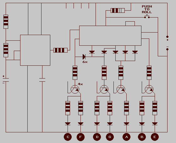
Electronic Dice
The 555 timer IC is connected for Astable Operation, the clock pulses are fed to the 4017 IC via the 10K resistor. The 4017 is a 10 stage counter, output 6 (pin 5) is connected to RESET (pin 15), thus...

DIY video dolly stepper motor driver
The commonly used 555 timer is configured for a variable mark/space ratio, which is essential for this application. Additionally, two D-type flip-flops (4013) are employed to provide the necessary count for the ULN2003 stepper motor driver. ULN2003 components may be...
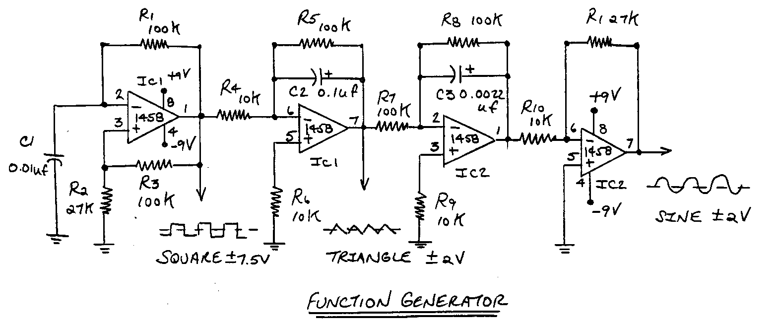
monitor an input pulse train
This circuit functions as a missing pulse detector, utilized in the General Purpose Controller Board with Basic Stamp 1. It monitors an input pulse train, and when a pulse is missed, the output of the 555 timer switches to a...

High-Current Battery Discharger
If you have a diverse assortment of 12V batteries in different conditions, this straightforward circuit will enable you to easily assess their capacity.
This circuit is designed to evaluate the capacity of 12V batteries, which may be in varying states...

Advanced LED Flasher with 555
This circuit uses three easily available 555 timer ICs. All three work as astable multivibrators. The first 555 has an on period and off period equal to 1 sec. This IC controls the on/ off periods of the other 2...

Simple Pulse Generator by IC 555 Timer
This is a simple pulse generator circuit or standard astable oscillator circuit for the IC 555 timer, NE555N IC.
The astable oscillator circuit utilizing the NE555 timer IC serves as a versatile pulse generator, producing a continuous square wave output....

AC time delay circuit with 555
Described timer to participate in the current circuit switch - bulb without any modification of existing pipelines. Connect the timer is in Figure 1 The time switch has only two outlets, which is connected in parallel to the button (Fig....

555 Capacitor Tolerance Adjustment circuit
The 555 Timer is configured as an astable multivibrator. Additional components have been incorporated to enhance circuit operation. Upon powering the circuit, the 555 Timer will generate a square wave, determined by the values of Capacitor C1 and Resistors R1...
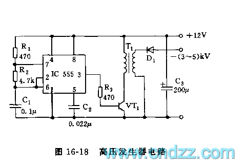
555 high voltage generator circuit
The high voltage generator depicted in figure 16-18 utilizes the 555 timer IC as its primary component. The oscillating voltage produced is enhanced through a step-up transformer. The astable multivibrator configuration comprises the 555 timer along with resistors R1 and...