


24 Volt Battery Box Vent Fan Control Circuit
#24 volt
#battery bank
#vent fan
#hydrogen venting
#brushless fan
#inverter
#charging
#backup system
#safety
#control circuit

Description: One of the backup systems utilizes a Magnum MS-PAE 4024 inverter, which lacks a built-in fan controller. Since batteries emit hydrogen during both normal and equalization charging, it is crucial to ventilate the batteries to the outside using a brushless fan. This circuit effectively manages this task for a 24-volt battery bank. The operation of the circuit is as follows: Battery voltage is fed directly to the LM358 operational amplifier and the variable resistor P1-R1. P1 determines the trip point at which the fan activates. The variable resistor VR1 and resistors R2 and R3 provide a stable reference voltage for the operational amplifier. Resistor R4 introduces hysteresis to prevent the fan from rapidly cycling on and off when near the trip point. The 4-volt Zener diode ensures that transistor Q1 turns off completely, as the output does not reach the supply rails. Resistors R5 and R6 ensure that Q1 operates fully in both the on and off states. Q1 is rated for fans drawing up to 100 milliamps of current. For larger fans, it is advisable to use Q1 to control a relay. This circuit is not compatible with 12-volt or 48-volt systems, but designs for those may be considered if there is sufficient interest.
The circuit effectively manages the cooling of a 24-volt battery bank by using a simple but efficient control mechanism. The LM358 operational amplifier serves as the heart of the circuit, allowing for precise control over the fan operation based on the battery voltage. The variable resistor P1 allows for user adjustment of the trip point, enabling customization based on specific battery characteristics or environmental conditions.
The reference voltage stability provided by VR1, R2, and R3 is critical for ensuring consistent performance of the op-amp. This stability is particularly important in battery management systems where voltage variations can occur due to load changes or charging cycles. The hysteresis introduced by R4 is a key feature that prevents the fan from toggling rapidly, which can lead to wear and tear on the fan and reduce its lifespan.
The inclusion of a 4-volt Zener diode ensures that the Q1 transistor is fully turned off when not in operation, preventing any unintended current flow that could lead to overheating or inefficiency. The design allows Q1 to switch fans rated for up to 100 milliamps directly, making it suitable for smaller brushless fans. For applications requiring higher current fans, the circuit can easily be adapted by incorporating a relay that is activated by Q1, allowing for the control of larger loads without compromising the integrity of the original circuit.
Overall, this circuit design represents an effective solution for managing battery ventilation in a 24-volt system, promoting safety and longevity of the battery while ensuring efficient operation of the connected fan. Further developments could explore similar designs for 12-volt and 48-volt systems, expanding the applicability of this fan control circuit.One of my backup systems uses a Magnum MS-PAE 4024 inverter, which doesn`t have any built-in fan controller. Since batteries give off hydrogen during both normal and equalization charging, it`s important to vent the batteries to the outside with a brushless fan.
This little circuit does the job nicely for a 24 volt battery bank. Here`s how the cir cuit works: Battery voltage comes in and goes directly to the LM358 op-amp and P1-R1. P1 sets the trip point where the fan will turn on. VR1 and R2-R3 provide a stable reference voltage for the op-amp. R4 adds some hysteresis so the fan doesn`t cycle on/off when near the trip point. the 4 volt zener assures that Q1 turns fully off, since the output doesn`t swing to the rails. R5-R6 assure that Q1 turns on/off completely. Q1 is good for fans that use up to 100 milliamps of current. If you have a bigger fan, use Q1 to turn on a relay This won`t work for 12 volt or 48 volt systems, but I might design those if there`s any interest here . Enjoy!
The circuit effectively manages the cooling of a 24-volt battery bank by using a simple but efficient control mechanism. The LM358 operational amplifier serves as the heart of the circuit, allowing for precise control over the fan operation based on the battery voltage. The variable resistor P1 allows for user adjustment of the trip point, enabling customization based on specific battery characteristics or environmental conditions.
The reference voltage stability provided by VR1, R2, and R3 is critical for ensuring consistent performance of the op-amp. This stability is particularly important in battery management systems where voltage variations can occur due to load changes or charging cycles. The hysteresis introduced by R4 is a key feature that prevents the fan from toggling rapidly, which can lead to wear and tear on the fan and reduce its lifespan.
The inclusion of a 4-volt Zener diode ensures that the Q1 transistor is fully turned off when not in operation, preventing any unintended current flow that could lead to overheating or inefficiency. The design allows Q1 to switch fans rated for up to 100 milliamps directly, making it suitable for smaller brushless fans. For applications requiring higher current fans, the circuit can easily be adapted by incorporating a relay that is activated by Q1, allowing for the control of larger loads without compromising the integrity of the original circuit.
Overall, this circuit design represents an effective solution for managing battery ventilation in a 24-volt system, promoting safety and longevity of the battery while ensuring efficient operation of the connected fan. Further developments could explore similar designs for 12-volt and 48-volt systems, expanding the applicability of this fan control circuit.One of my backup systems uses a Magnum MS-PAE 4024 inverter, which doesn`t have any built-in fan controller. Since batteries give off hydrogen during both normal and equalization charging, it`s important to vent the batteries to the outside with a brushless fan.
This little circuit does the job nicely for a 24 volt battery bank. Here`s how the cir cuit works: Battery voltage comes in and goes directly to the LM358 op-amp and P1-R1. P1 sets the trip point where the fan will turn on. VR1 and R2-R3 provide a stable reference voltage for the op-amp. R4 adds some hysteresis so the fan doesn`t cycle on/off when near the trip point. the 4 volt zener assures that Q1 turns fully off, since the output doesn`t swing to the rails. R5-R6 assure that Q1 turns on/off completely. Q1 is good for fans that use up to 100 milliamps of current. If you have a bigger fan, use Q1 to turn on a relay This won`t work for 12 volt or 48 volt systems, but I might design those if there`s any interest here . Enjoy!

12 Vdc - 120 Vac Inverter
An Inverter is a device that converts 12 volts d.c to 120 volts a.c., which is what we use in our homes. This project will handle about 300 watts, which is perfect for lights, small T.V.s and radio equipment. This...

Two inverter controlled synchronous motor of the second circuit
Adjust the potentiometers RPi and RPz to modify the speed of two motors.
The circuit utilizes two potentiometers, designated as RPi and RPz, to control the speed of two separate motors. Each potentiometer is connected in a voltage divider configuration, enabling...

inverter circuit
This inverter is designed to operate appliances such as TVs and stereos while traveling or camping. It converts 12 VDC to 120 VAC, with the output wattage determined by the transistors used for Q1 and Q2, as well as the...

12 vdc to 240 vac inverter
This 12 VDC to 240 VAC inverter circuit does not utilize specialized components, such as the toroidal transformer commonly found in many inverter circuits.
The inverter circuit described is designed to convert a 12 VDC input into a 240 VAC output...
Super Simple Inverter
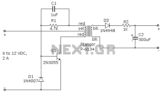
This is an example of a simple inverter that can be used to power a fluorescent lamp and a small strobe. This circuit will produce over 400 VDC from a 12 VDC, 2.5 A.
The described inverter circuit is designed to...

100W Inverter Circuit 12VDC to 220VAC
The schematic diagram of a 100W inverter circuit converts a 12V DC input into a 220V AC output. The circuit is built using the IC CD4047 to generate a 50Hz sine wave signal. The power transistor 2N3055 amplifies the signal...

On-off-inverters
Each time the switch is closed, the voltage across capacitor C1 causes inverter A to change state, with positive feedback from inverter B. Resistor R1 delays the charging and discharging of C1, rendering the circuit nearly immune to contact bounce....

Inverter size strength
The differences in strengths between PMOS and NMOS transistors can be observed through a simple test by gradually increasing the input voltage and noting the point at which the output voltage changes from 5V to 0V. To conduct this test,...

Bedside lamp with CD production delay
The FIG inverter I, II, along with resistors R1, R2, capacitor CI, and switch SB, forms a bistable trigger switch. Each time switch SB is activated, the output level of anti-phase II changes. The circuit includes components R3, C2, and...