


3.6 Volt Lithium Ion Battery Charger (PIC12F675)
#lithium ion
#battery charger
#PIC12F675
#3.6 volt
#energy
#microcontroller
#power management
#rechargeable
#voltage regulation

Description: Lithium Ion batteries pack a lot of power by weight compared to other types. There are 2 things that need to be handled differently than nicad or NiMH. They cannot be used as a direct substitute (even if they look like other AA's) since they run at about 3.6 (or so) volts. They cannot be charged in the same way as nicad or NiMH. More: Normally, you put in a specified current (about 0.2C) until 4.2 volts is reached. Then, you keep the voltage tightly regulated at 4.2 volts until the charge rate drops to 10 percent (about 0.02C).
This design uses a regulated supply for both parts of the charging. Only the charging current is monitored since the supply voltage is maintained at 4.2 volts. The charging current is controlled using variable pulse width of the voltage feed.
Lithium-ion batteries are known for their high energy density and efficiency, making them a popular choice for portable electronics. However, their charging requirements differ significantly from those of nickel-cadmium (NiCd) and nickel-metal hydride (NiMH) batteries. The nominal voltage of a lithium-ion cell is approximately 3.6 volts, which necessitates a dedicated charging circuit that can handle this voltage without exceeding it, as doing so can lead to battery damage or even catastrophic failure.
The charging process for lithium-ion batteries typically involves two main phases: constant current (CC) and constant voltage (CV). Initially, a constant current is applied, usually set at around 0.2C, until the battery voltage reaches the maximum threshold of 4.2 volts. This phase is crucial for safely bringing the battery up to full capacity. Once the voltage limit is reached, the charger transitions to the constant voltage phase, where the voltage is maintained at 4.2 volts. During this phase, the charging current gradually decreases until it drops to around 10% of the initial charging rate, approximately 0.02C, indicating that the battery is fully charged.
To implement this charging strategy, a regulated power supply is essential. The design should include a voltage regulation circuit that can maintain the output at 4.2 volts with minimal fluctuation. The charging current can be controlled through pulse width modulation (PWM), which allows for fine-tuning of the current supplied to the battery. This method provides a means to adjust the average current delivered to the battery while keeping the voltage constant.
It is critical to incorporate safety features into the design, such as overvoltage protection, temperature monitoring, and current limiting, to mitigate the risks associated with lithium-ion battery charging. Failure to adhere to proper charging protocols can result in overheating, swelling, or even explosions, underscoring the importance of a well-engineered charging circuit. The design should be rigorously tested to ensure compliance with safety standards and to confirm the reliability of the charging process.Lithium Ion batteries pack a lot of power by weight compared to other types. There are 2 things that need to be handled differently than nicad on NiMH. They cannot be used as a direct substitute (even if they look like other AA's) since they run at about 3.6 (or so) volts. They cannot be charged in the same way as nicad or NiMH. Normally, you put in a specified current (about 0.2C) until 4.2 volts is reached. Then, you keep the voltage tightly regulated at 4.2 volts until the charge rate drops to 10 percent (about 0.02C). This design uses a regulated supply for both parts of the charging. Only the charging current is monitored since the supply voltage is maintained at 4.2 volts. The charging current is controlled using variable pulse width of the voltage feed. Please Note: This type of battery is known to Explode if charged in the wrong way. It's up to you to decide if making this type of charger is within your technical abilites.
This design uses a regulated supply for both parts of the charging. Only the charging current is monitored since the supply voltage is maintained at 4.2 volts. The charging current is controlled using variable pulse width of the voltage feed.
Lithium-ion batteries are known for their high energy density and efficiency, making them a popular choice for portable electronics. However, their charging requirements differ significantly from those of nickel-cadmium (NiCd) and nickel-metal hydride (NiMH) batteries. The nominal voltage of a lithium-ion cell is approximately 3.6 volts, which necessitates a dedicated charging circuit that can handle this voltage without exceeding it, as doing so can lead to battery damage or even catastrophic failure.
The charging process for lithium-ion batteries typically involves two main phases: constant current (CC) and constant voltage (CV). Initially, a constant current is applied, usually set at around 0.2C, until the battery voltage reaches the maximum threshold of 4.2 volts. This phase is crucial for safely bringing the battery up to full capacity. Once the voltage limit is reached, the charger transitions to the constant voltage phase, where the voltage is maintained at 4.2 volts. During this phase, the charging current gradually decreases until it drops to around 10% of the initial charging rate, approximately 0.02C, indicating that the battery is fully charged.
To implement this charging strategy, a regulated power supply is essential. The design should include a voltage regulation circuit that can maintain the output at 4.2 volts with minimal fluctuation. The charging current can be controlled through pulse width modulation (PWM), which allows for fine-tuning of the current supplied to the battery. This method provides a means to adjust the average current delivered to the battery while keeping the voltage constant.
It is critical to incorporate safety features into the design, such as overvoltage protection, temperature monitoring, and current limiting, to mitigate the risks associated with lithium-ion battery charging. Failure to adhere to proper charging protocols can result in overheating, swelling, or even explosions, underscoring the importance of a well-engineered charging circuit. The design should be rigorously tested to ensure compliance with safety standards and to confirm the reliability of the charging process.Lithium Ion batteries pack a lot of power by weight compared to other types. There are 2 things that need to be handled differently than nicad on NiMH. They cannot be used as a direct substitute (even if they look like other AA's) since they run at about 3.6 (or so) volts. They cannot be charged in the same way as nicad or NiMH. Normally, you put in a specified current (about 0.2C) until 4.2 volts is reached. Then, you keep the voltage tightly regulated at 4.2 volts until the charge rate drops to 10 percent (about 0.02C). This design uses a regulated supply for both parts of the charging. Only the charging current is monitored since the supply voltage is maintained at 4.2 volts. The charging current is controlled using variable pulse width of the voltage feed. Please Note: This type of battery is known to Explode if charged in the wrong way. It's up to you to decide if making this type of charger is within your technical abilites.
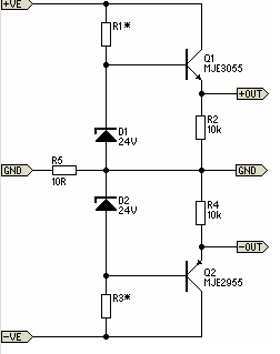
Simple Pre-Regulator
There will be many occasions when it is beneficial to utilize the P05 supply module sourced from a higher voltage supply. For instance, this could be advantageous when integrating balanced inputs.
The P05 supply module is designed to facilitate the conversion...

Digital Slave Flash Trigger PIC 12F675
The Slave Flash Trigger is activated by pressing a push button. When activated, the indicator lamp emits one to three flickers to indicate the programmed mode. One flicker means the flash will fire with each flash, two flickers indicate the...

Driving circuit schematic
The driving circuit depicted in Figure 18-12 consists of a connection between the driving portion, the microcontroller, and the air conditioning operation components of the bridge. The microcontroller's digital signal levels from ports P4.0 to P4.3 (approximately 12 feet) and...

Battery charging regulator
The circuit is designed to charge a 12-volt component selection at a maximum current of six amperes. Once the battery voltage reaches its fully charged level, the SCR shuts off, and a trickle charge, determined by the resistance value of...

Robo Atmega328p project
This project was designed to introduce a friend to microcontrollers and circuits using various functionalities and spare parts. A PS2 numpad was utilized as the key entry mechanism, which was found at a thrift store and included the necessary connector....

Tensor Energy Coils
The concept of quadrature involves three manipulable forces rather than the two traditionally considered in electromagnetism. The electric field exhibits both positive and negative voltages, while the magnetic field consists of north and south poles. Additionally, the tempic field encompasses...

How to Design Battery Charger Applications that Require External Microcontrollers and Related System-Level Issues
Application note on designing linear and switch-mode (switching DC-DC converter current source) battery charger applications that require external microcontrollers and related system-level issues for notebook computers.
The application note provides guidance on the design of both linear and switching DC-DC converter...

10 or more switches using a microcontroller
There are several methods to read multiple switch inputs using a reduced number of microcontroller unit (MCU) pins. One approach involves using an analog MCU pin to read multiple switches by assigning a unique voltage to each switch through a...

Regulator circuit silicon resistor formed
The simple voltage regulator circuit consists of a silicon regulator and a resistor. It is designed to rectify and filter DC voltage, as illustrated in the accompanying figure. The voltage regulator is connected in parallel with the load, and the...