


Automatic Ni-Cd Battery ChargerCircuit
#Ni-Cd
#NE555
#automatic charging
#Zener diode
#voltage comparator
#battery management
#charging circuit
#energy
#power supply

Description: An automatic Ni-Cd battery charger circuit is depicted in the provided image. The internal comparator of the NE555 timer is configured to a reference voltage of 4.7V using a Zener diode. When the voltage at pin 6 exceeds this value, the output at pin 3 decreases. Conversely, if the voltage at pin 2 falls below half of the reference voltage, the output voltage increases. When the voltage of the...
The automatic Ni-Cd battery charger circuit utilizes the NE555 timer IC in a comparator configuration to regulate the charging process. The Zener diode is employed to establish a stable reference voltage of 4.7V, which is crucial for determining the charging state of the battery. This reference voltage is connected to pin 6 of the NE555, while the voltage at pin 2 is monitored to assess the battery's charge level.
During operation, if the voltage at pin 6 surpasses 4.7V, the output at pin 3 transitions to a low state, signaling a reduction in the charging current to prevent overcharging. This feature is essential for maintaining the longevity and safety of the Ni-Cd batteries. On the other hand, if the voltage at pin 2 drops below half of the reference voltage (approximately 2.35V), the NE555 output at pin 3 will increase, allowing more current to flow into the battery for charging.
The circuit typically includes additional components such as resistors and capacitors to ensure stable operation and to filter out any noise that might affect the performance of the NE555 timer. A diode may also be included to prevent reverse current flow, protecting the circuit and the battery from damage.
In summary, this automatic Ni-Cd battery charger circuit effectively monitors and controls the charging process through the use of the NE555 timer IC, ensuring safe and efficient charging of the batteries while extending their operational life.Automatic Ni-Cd Battery Charger circuit is shown in the above picture. The internal comparator of NE555 is set as 4.7V by Zener diode. If the potential of pin 6 becomes higher than this value, the output of pin 3 become lower; if the potential of pin 2 is lower than half of the reference voltage, the output voltage becomes higher,. When the voltage of the..
The automatic Ni-Cd battery charger circuit utilizes the NE555 timer IC in a comparator configuration to regulate the charging process. The Zener diode is employed to establish a stable reference voltage of 4.7V, which is crucial for determining the charging state of the battery. This reference voltage is connected to pin 6 of the NE555, while the voltage at pin 2 is monitored to assess the battery's charge level.
During operation, if the voltage at pin 6 surpasses 4.7V, the output at pin 3 transitions to a low state, signaling a reduction in the charging current to prevent overcharging. This feature is essential for maintaining the longevity and safety of the Ni-Cd batteries. On the other hand, if the voltage at pin 2 drops below half of the reference voltage (approximately 2.35V), the NE555 output at pin 3 will increase, allowing more current to flow into the battery for charging.
The circuit typically includes additional components such as resistors and capacitors to ensure stable operation and to filter out any noise that might affect the performance of the NE555 timer. A diode may also be included to prevent reverse current flow, protecting the circuit and the battery from damage.
In summary, this automatic Ni-Cd battery charger circuit effectively monitors and controls the charging process through the use of the NE555 timer IC, ensuring safe and efficient charging of the batteries while extending their operational life.Automatic Ni-Cd Battery Charger circuit is shown in the above picture. The internal comparator of NE555 is set as 4.7V by Zener diode. If the potential of pin 6 becomes higher than this value, the output of pin 3 become lower; if the potential of pin 2 is lower than half of the reference voltage, the output voltage becomes higher,. When the voltage of the..

0-12V 2A power supply
This project has two options. It can be a mains operated project, using a 2155 or 2156 transformer or it can be connected to a plug pack. We recommend it be connected to a 16v AC 1 amp plug pack...

Digital pulse counter
This is a simple yet versatile pulse counting and smoothing integrator circuit featuring an NE555 timer as the waveform shaper and a small LCD display for output. Originally designed for counting pulses from Geiger counters, it includes a piezo speaker...

Output sampling winding isolated switching power supply
The diagram illustrates the output sampling winding of an isolated switching power supply. In the diagram, T represents a high-frequency transformer; N2 denotes the self-oscillation positive feedback winding; N3 is the error amplifier; VTS is the winding that provides the...

MAX668 16V 4.4A switching power supply circuit design electronic project
A simple 16-volt switching power supply circuit can be constructed using the provided diagram, which is based on the MAX668 constant-frequency, pulse-width modulating (PWM), current-mode DC-DC controller. This integrated circuit is designed for a wide range of DC-DC conversion applications...

Voltage Regulator Using Zener Diode Circuit
A Zener diode regulator is a fundamental electronic circuit valuable for hobbyists. This circuit provides a regulated output voltage, suitable for biasing other circuit components. The Zener diode operates in the reverse breakdown region, maintaining a nearly constant voltage regardless...

Ni-Cd Baterry Charger 12-18V
A clever charger circuit that safely charges any Ni-Cd battery. It offers charge current selection, polarization detection, protection, and the ability to connect multiple batteries in series. Ni-Cd batteries can be recharged more than 1000 times before becoming unusable. The...

Power Supply for P.A. Class40
For its maximum result, the final stage of the amplifier should have the proper power supply, as the flowing currents are very high. A Class A amplifier requires attention. These are the rules for the power supply for the Class...

Simple-power-supply
This power supply provides both +9 V and -9 V outputs to replace two 9-V batteries. The rectifier circuit consists of two separate full-wave rectifiers, each connected to the secondary winding of the transformer. The first full-wave rectifier, made up...
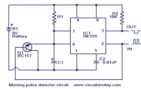
Missing pulse detector circuit using NE555
An NE555 timer integrated circuit (IC) configured in a specific manner can identify the absence of a pulse or an unusually long duration between two successive pulses in a pulse train. Such circuits are applicable for detecting the intermittent operation...