


Battery Test Circuit Circuit
#battery test
#voltage monitoring
#LED indicator
#voltage levels
#1-Hz blinking
#steady glow
#11V-15V range
#high voltage alert
#low voltage alert

Description: This circuit displays three voltage levels: normal (11 to 15 V), high (greater than 15 V), and low (below 11 V). When the voltage is low, the LED illuminates steadily. In the normal voltage range, the LED remains off. When the voltage is high, the LED blinks at a rate of 1 Hz. This circuit is beneficial for ensuring proper operation of electrical systems.
The circuit employs a voltage comparator to monitor the input voltage and determine its level. The reference voltages for low and high thresholds can be set using a voltage divider network, which typically consists of resistors. For the low voltage threshold (11 V), the circuit can be designed using an operational amplifier configured as a comparator. When the input voltage drops below this threshold, the output of the comparator switches, turning the LED on steadily to indicate a low voltage condition.
In the normal voltage range (11 to 15 V), the comparator output remains low, keeping the LED off. To detect the high voltage condition (greater than 15 V), a second comparator can be implemented. This comparator would be configured to activate when the input voltage exceeds the high threshold. Upon activation, a timer circuit, such as a 555 timer in astable mode, can be integrated to cause the LED to blink at a frequency of 1 Hz, providing a visual indication of the high voltage status.
The circuit's design ensures that it can handle a range of input voltages while providing clear visual feedback through the LED. Additionally, the use of appropriate resistors and capacitors will stabilize the circuit operation and prevent false triggering due to transient voltage spikes. This voltage level indicator circuit serves as a critical tool in monitoring electrical systems, ensuring they operate within safe voltage ranges, and alerting users to potential issues before they escalate. Using this circuit, tiiree levels of voltage can be displayednormal (11 to 15 V), liigh (>15 V), and low (11 V). When the voltage is low, the LED glows steadily. In the normal range, the LED is off. When the voltage is high, the LED blinks at a 1-Hz rate. This circuit is useful for assuring proper electrical system operation.
The circuit employs a voltage comparator to monitor the input voltage and determine its level. The reference voltages for low and high thresholds can be set using a voltage divider network, which typically consists of resistors. For the low voltage threshold (11 V), the circuit can be designed using an operational amplifier configured as a comparator. When the input voltage drops below this threshold, the output of the comparator switches, turning the LED on steadily to indicate a low voltage condition.
In the normal voltage range (11 to 15 V), the comparator output remains low, keeping the LED off. To detect the high voltage condition (greater than 15 V), a second comparator can be implemented. This comparator would be configured to activate when the input voltage exceeds the high threshold. Upon activation, a timer circuit, such as a 555 timer in astable mode, can be integrated to cause the LED to blink at a frequency of 1 Hz, providing a visual indication of the high voltage status.
The circuit's design ensures that it can handle a range of input voltages while providing clear visual feedback through the LED. Additionally, the use of appropriate resistors and capacitors will stabilize the circuit operation and prevent false triggering due to transient voltage spikes. This voltage level indicator circuit serves as a critical tool in monitoring electrical systems, ensuring they operate within safe voltage ranges, and alerting users to potential issues before they escalate. Using this circuit, tiiree levels of voltage can be displayednormal (11 to 15 V), liigh (>15 V), and low (11 V). When the voltage is low, the LED glows steadily. In the normal range, the LED is off. When the voltage is high, the LED blinks at a 1-Hz rate. This circuit is useful for assuring proper electrical system operation.
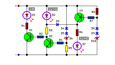
Battery Voltage Indicator
This circuit monitors battery voltage and features a three-LED display. By connecting this circuit to the battery of a vehicle, users can easily determine the approximate voltage at a glance.
The battery voltage monitoring circuit utilizes a simple yet effective design...

Simple circuit shuts off system when supply voltage is low
When the supply voltage drops below a minimum threshold, it is often advisable to disconnect the supply from the system to prevent poor performance or erratic operation. The circuit presented achieves this with minimal cost, board space, and complexity. Additionally,...
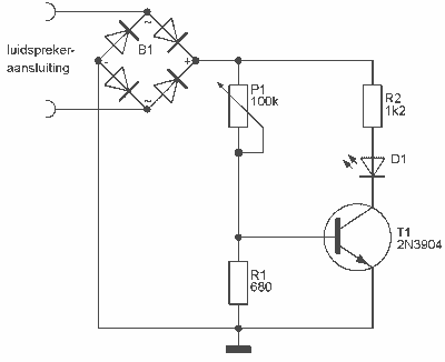
Audio Peak / Beat LED indicator
This indicator can be used, or see if your speakers can be damaged by the noise power. With P1 you can set the limit to which D1 LED lights. The pot is 100k here, you can even experiment with other...

Monitoring Voltages with Scaling Circuits
The UCD90124/A is utilized to monitor multiple voltages, some of which exceed 2.5V. Scaling circuits are implemented to prevent exceeding the 2.5V maximum on the MON inputs. The inquiry pertains to whether raw voltage values or scaled values should be...
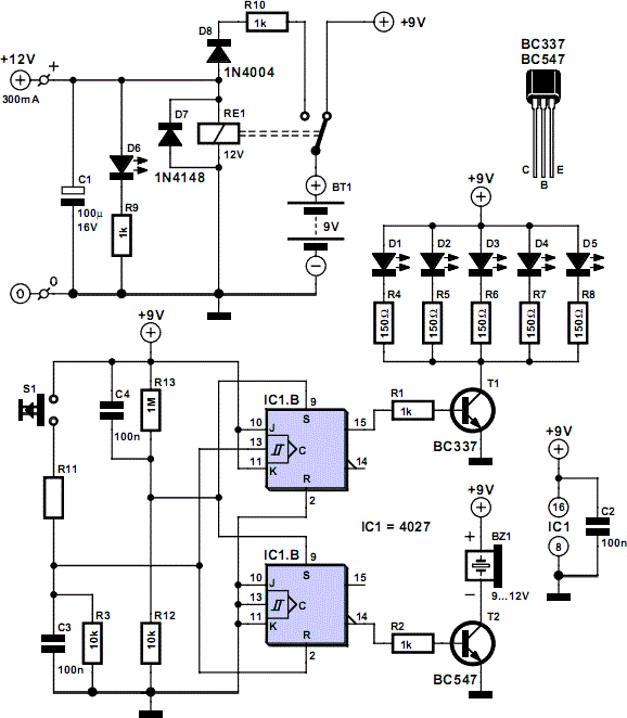
Mains Voltage Monitor
When the push button is pressed, a clock pulse appears on the CLK input of flip-flop IC1b. The output then toggles, causing the LEDs to turn off. Simultaneously, IC1a is reset, silencing the buzzer. Pressing the button again will turn...

DC supply voltage the more limited indication circuit
When the supply voltage falls below 10.2V, the yellow light-emitting diode (LED) VLi illuminates, indicating that the storage pool can no longer continue to discharge. Additionally, when the voltage exceeds 16.2V, the yellow, green, and red light-emitting diodes (LEDs) VLi,...

Linear LTC4151 Voltage
This power monitoring device accurately measures voltage and current on a positive supply rail ranging from 7V to 80V through a straightforward I2C interface, as specified in the datasheet. It is particularly suitable for automotive applications that require power monitoring...

simple supply voltage monitor
A circuit for monitoring supply voltages of ±5 V and ±12 V can be constructed as shown in the diagram. It is significantly simpler than the typical monitors that utilize comparators and AND gates. The circuit is not designed to...

Digital Main Voltage Indicator
Continuous monitoring of mains voltage is essential in various applications, including manual voltage stabilizers and motor pumps. Although an analog voltmeter is cost-effective, it has several drawbacks due to its moving parts and sensitivity to vibrations. The solid-state voltmeter circuit...