


car charger for nicd battery packs
#car charger
#NiCd battery
#power supply
#constant current
#12V battery
#battery pack
#charging circuit
#automotive
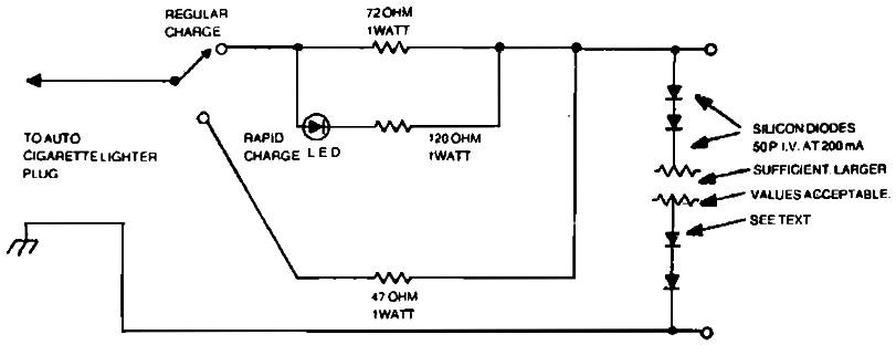
Description: Car charger for NiCd battery packs power supply. This is a car NiCd battery charger circuit that can charge any Ni-Cd battery between 4.8 and 4.4 volts from a classic 12 volts car battery. The charging current is constant and can be selected from the values of 50 to 120 mA using a selector switch. This feature is particularly useful for model-making enthusiasts, video operators, and users of small appliances for transmission and reception, as well as for anyone utilizing Ni-Cd batteries who need to recharge when a voltage network is not available.
The described circuit functions as a dedicated car charger for nickel-cadmium (NiCd) battery packs, specifically designed to operate from a standard 12-volt automotive battery. It is capable of charging NiCd batteries with a nominal voltage range of 4.4 to 4.8 volts, making it suitable for various applications, including model making and portable electronic devices.
The circuit incorporates a constant current charging mechanism, which is essential for the safe and efficient charging of NiCd batteries. The charging current can be adjusted between 50 mA and 120 mA through a selector switch, allowing users to choose the appropriate current based on the specific requirements of the battery being charged. This feature enhances the versatility of the charger, accommodating different battery capacities and charge times.
Additionally, the design is particularly advantageous for users in situations where conventional power sources are unavailable. For instance, model-making enthusiasts and video operators often require reliable power solutions while on the move. The ability to charge batteries directly from a vehicle's electrical system ensures that users can maintain power for their devices without the need for external charging stations.
The circuit diagram for this charger typically includes essential components such as diodes for rectification, voltage regulators to maintain the desired output voltage, and capacitors for smoothing the output. It is crucial to ensure that the components selected are rated appropriately for automotive applications, considering factors such as temperature variations and vibration.
Overall, this car charger circuit is a practical solution for efficiently recharging NiCd batteries in various scenarios, providing a dependable power source for users reliant on these battery types.Car charger for Nicd Battery Packs power supply. Go to that page to read the explanation about above power supply related circuit diagram. This is a car nicd battery charger circuitthat can chargeanyNi-Cdbatterybetween 4. 8 and4. 4 voltsfromaclassic12Voltscar battery. Thecharging currentis constantitcan besel ected from the values of 50 to120mAbythe selectorS. This feature is veryuseful formodel makingenthusiasts, forvideooperators, to those who usesmall appliancestransmissionandreceptionto all thosethat useNi-Cdbatteriesand needto rechargeorvoltagenetworkis not available. .
The described circuit functions as a dedicated car charger for nickel-cadmium (NiCd) battery packs, specifically designed to operate from a standard 12-volt automotive battery. It is capable of charging NiCd batteries with a nominal voltage range of 4.4 to 4.8 volts, making it suitable for various applications, including model making and portable electronic devices.
The circuit incorporates a constant current charging mechanism, which is essential for the safe and efficient charging of NiCd batteries. The charging current can be adjusted between 50 mA and 120 mA through a selector switch, allowing users to choose the appropriate current based on the specific requirements of the battery being charged. This feature enhances the versatility of the charger, accommodating different battery capacities and charge times.
Additionally, the design is particularly advantageous for users in situations where conventional power sources are unavailable. For instance, model-making enthusiasts and video operators often require reliable power solutions while on the move. The ability to charge batteries directly from a vehicle's electrical system ensures that users can maintain power for their devices without the need for external charging stations.
The circuit diagram for this charger typically includes essential components such as diodes for rectification, voltage regulators to maintain the desired output voltage, and capacitors for smoothing the output. It is crucial to ensure that the components selected are rated appropriately for automotive applications, considering factors such as temperature variations and vibration.
Overall, this car charger circuit is a practical solution for efficiently recharging NiCd batteries in various scenarios, providing a dependable power source for users reliant on these battery types.Car charger for Nicd Battery Packs power supply. Go to that page to read the explanation about above power supply related circuit diagram. This is a car nicd battery charger circuitthat can chargeanyNi-Cdbatterybetween 4. 8 and4. 4 voltsfromaclassic12Voltscar battery. Thecharging currentis constantitcan besel ected from the values of 50 to120mAbythe selectorS. This feature is veryuseful formodel makingenthusiasts, forvideooperators, to those who usesmall appliancestransmissionandreceptionto all thosethat useNi-Cdbatteriesand needto rechargeorvoltagenetworkis not available. .

fireworks controller circuit
A 12V battery pack from a PowerWheels car is used alongside two wooden planks with several nails driven through them. Each nail is wrapped with speaker wire that connects to ignitors, while the other end returns to a central positive...

Comparison of various circuit diagram VI conversion and a constant current source
The circuit is designed to provide several constant current outputs to the load resistor RL. The first RL is floating and is rarely utilized. The second RL serves as a virtual ground and is not commonly used either. The third...

car battery charger schematics
The circuit is designed to be powered directly by a power supply, which is why it does not include a transformer, rectifier, or filter capacitors in the schematic. However, the addition of these components is possible. To operate the circuit,...
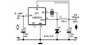
Switch Mode Power Supply
National Semiconductor has been producing and designing integrated circuits (ICs) for use in switch-mode power supplies for many years. The application of these devices is standard.
National Semiconductor has established a significant presence in the design and manufacturing of integrated circuits...

Automotive burglar alarm
The alarm activates after a 13-second delay and remains active for 1 to 1.5 minutes before automatically resetting. It can also be deactivated and reset by opening and reclosing switch SI.
The described circuit functions as a delay-triggered alarm system, incorporating...

12V Battery to 220V Power Inverter charge controller
A power inverter converts direct current (DC) power to standard alternating current (AC) power. The following schematic illustrates a 12V power inverter circuit diagram.
The 12V power inverter circuit typically consists of several key components that work together to achieve the...

power supply alarm circuit
Most of the power supply failure indicator circuits need a separate power supply for themselves. But the alarm circuit presented here needs no additional supply source. It employs an electrolytic capacitor to store adequate charge, to feed power to the...

Output sampling winding isolated switching power supply
The diagram illustrates the output sampling winding of an isolated switching power supply. In the diagram, T represents a high-frequency transformer; N2 denotes the self-oscillation positive feedback winding; N3 is the error amplifier; VTS is the winding that provides the...
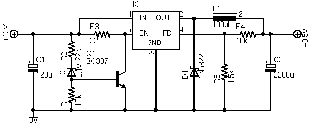
ASUS Eee Car Charger
The ASUS Eee is an ultra-portable notebook that meets the essential needs of tech enthusiasts while maintaining excellent build quality and affordability. In New Zealand, it can be purchased exclusively from DSE, where it is competitively priced compared to importing,...