


Chager circuit for SMF batteries
#SMF batteries
#voltage regulated
#current regulated
#1.2 AH
#sealed maintenance free
#charger circuit
#battery charging
#DIY charger
#electronics project
#power management
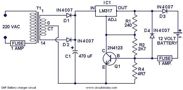
Description: This is a simple charger circuit designed for charging sealed maintenance-free (SMF) batteries. The circuit is both current and voltage regulated, making it safe for charging SMF batteries with a rating of 1.2 AH. It can be modified slightly to accommodate various types of SMF batteries. The circuit consists of a power supply section made up of transformer T1 and diodes D1 and D2. Capacitor C1 filters the output from the rectifier. The next section includes IC1 and Q1, which provide the necessary voltage and current regulation. Diode D3 prevents reverse current flow from the battery. Resistor R4 determines the charging current, which is set to 120 mA in this configuration. The value of R4 can be adjusted according to the equation R4 = (0.6 V / Charging current) to charge batteries requiring different charging currents.
The charger circuit operates as follows: The transformer T1 steps down the AC voltage from the mains supply to a lower AC voltage suitable for charging. Diodes D1 and D2 are configured in a bridge rectifier arrangement, converting the AC voltage to a pulsating DC voltage. Capacitor C1 smooths this pulsating DC voltage, providing a more stable output for the subsequent regulation stages.
The regulation section consists of an integrated circuit (IC1), which is typically a voltage regulator, and a transistor (Q1) that is used to handle the required current. This configuration allows the circuit to maintain a consistent output voltage and current, essential for safely charging the battery without overcharging or damaging it.
Diode D3 is crucial as it prevents any backflow of current from the battery to the charger when the charger is not in operation, thus protecting the circuit components. The resistor R4 is a key component in determining the charging current. By using the formula R4 = (0.6 V / Charging current), it is possible to calculate the appropriate resistance value needed to achieve the desired charging current for different battery types. For instance, if a charging current of 100 mA is required, R4 would need to be approximately 6 ohms.
Overall, this charger circuit is a versatile solution for charging various SMF batteries, with the ability to adjust charging parameters through simple modifications. Proper attention to component ratings and configurations will ensure reliable and safe operation.Here is a simple charger circuit for charging SMF(sealed maintenance free ) batteries. The charger circuit being curernt and voltage regulated, can be safely used to charge SMF batteries of 1. 2 AH rating. This circuit was actually designed in response to a request from a reader. With slight modifications you can use it for charging any sort of SMF bat teries. The first part of the circuit is the power supply made of transformer T1 and diodes D1&D2. The capacitor C1 filters the rectifier output. The next part is the section comprising of IC1 and Q1 which provides the necessary volatge and current regulation. The diode D3 prevents ther reverse flow of charge from the battery. R4 is the component that determines the charging current. Here it is set to be 120 mA. R4= (0. 6 V/Charging current). By selecting the proper value of R4 according to equation, you can charge batteries that require different charging currents.
The charger circuit operates as follows: The transformer T1 steps down the AC voltage from the mains supply to a lower AC voltage suitable for charging. Diodes D1 and D2 are configured in a bridge rectifier arrangement, converting the AC voltage to a pulsating DC voltage. Capacitor C1 smooths this pulsating DC voltage, providing a more stable output for the subsequent regulation stages.
The regulation section consists of an integrated circuit (IC1), which is typically a voltage regulator, and a transistor (Q1) that is used to handle the required current. This configuration allows the circuit to maintain a consistent output voltage and current, essential for safely charging the battery without overcharging or damaging it.
Diode D3 is crucial as it prevents any backflow of current from the battery to the charger when the charger is not in operation, thus protecting the circuit components. The resistor R4 is a key component in determining the charging current. By using the formula R4 = (0.6 V / Charging current), it is possible to calculate the appropriate resistance value needed to achieve the desired charging current for different battery types. For instance, if a charging current of 100 mA is required, R4 would need to be approximately 6 ohms.
Overall, this charger circuit is a versatile solution for charging various SMF batteries, with the ability to adjust charging parameters through simple modifications. Proper attention to component ratings and configurations will ensure reliable and safe operation.Here is a simple charger circuit for charging SMF(sealed maintenance free ) batteries. The charger circuit being curernt and voltage regulated, can be safely used to charge SMF batteries of 1. 2 AH rating. This circuit was actually designed in response to a request from a reader. With slight modifications you can use it for charging any sort of SMF bat teries. The first part of the circuit is the power supply made of transformer T1 and diodes D1&D2. The capacitor C1 filters the rectifier output. The next part is the section comprising of IC1 and Q1 which provides the necessary volatge and current regulation. The diode D3 prevents ther reverse flow of charge from the battery. R4 is the component that determines the charging current. Here it is set to be 120 mA. R4= (0. 6 V/Charging current). By selecting the proper value of R4 according to equation, you can charge batteries that require different charging currents.

Computer Off Switch
How often does it happen that a user shuts down Windows and then forgets to turn off the computer? This circuit automates that process. After Windows is shut down, a click occurs a second later, disconnecting the PC from the...

A Power Management Interface Circuit For Telecom Hot Swap With Local Dc/dc Conve
New cellular phones have incorporated high-resolution cameras that require bright illumination of the surrounding area to achieve high-quality pictures. Traditional xenon-filled photo flashes cannot be used due to the limited space available in cellular phone cameras. Instead, design engineers utilize...

Control a processor`s power supply in real time
In battery-powered applications in which power management is key, a microprocessor may adjust its core voltage corresponding to an increase or a decrease in clock speed, allowing full processing power when necessary but not wasting excess power when idle. The...
battery charging indicator for
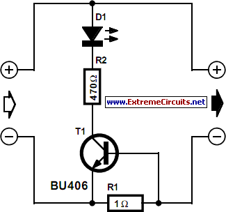
While owning a modern NiCd battery charger, there may still be instances where an incompatible battery is encountered, such as one with a unique voltage requirement or one that necessitates a higher charging current than what a standard charger can...

Mains Manager
It is common to forget to turn off peripherals such as monitors, scanners, and printers when shutting down a PC. Typically, these devices are connected to a four-way trailing socket, which is plugged into a wall outlet. If this outlet...
Split pack battery charging
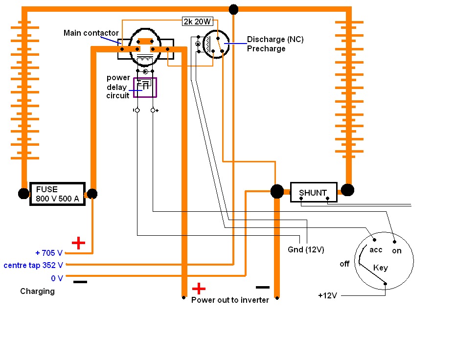
A high voltage battery pack will be utilized in both the eCRX and the electric race bike.
A high voltage battery pack is a critical component in electric vehicles, providing the necessary energy storage to power electric motors effectively. In the...

Power Path Management Battery Charger
Powering the system is required by many applications while charging the battery simultaneously. Interaction between the system and charger may result in a...
Power management in electronic systems is critical, particularly in applications that necessitate simultaneous operation and battery charging. This...
Power Path Management Battery Charger
Powering the system is required by many applications while charging the battery simultaneously. Interaction between the system and charger may result in a...
Power management in electronic systems is critical, particularly in applications that necessitate simultaneous operation and battery charging. This...
How to extend the battery life of your microcontroller based design
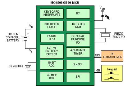
Battery-powered devices, such as electric toothbrushes, shavers, cell phones, PDAs, MP3 players, and remote controls, are integral to daily life. Consequently, power management has become a critical consideration for embedded designers. Microcontrollers (MCUs) provide various methods for managing power requirements...