


Charge Limiter circuit
#charge limiter
#dual charging
#wall charger
#battery management
#current limiting
#low current
#battery packs
#charging circuit

Description: Here is a deluxe version of the simple charge rate limiter, using the same idea but with the ability to charge two packs simultaneously from a single wall charger. For circuit description and parts list, see the simple charger page. Since wall chargers provide about 55 mA, you should not use this dual circuit to charge batteries at rates greater than 27 mA (for a total of 54 mA).
The deluxe charge rate limiter circuit is designed to efficiently manage the charging process of two battery packs simultaneously while ensuring that the total current drawn from the wall charger does not exceed its rated output. The circuit employs a dual-channel architecture, allowing each battery pack to be charged independently but with a common power source.
Key components of the circuit include two charge rate limiting resistors, which are crucial in controlling the charging current to each battery pack. These resistors are selected to allow a maximum charging current of 27 mA per pack, ensuring that the total current remains within the 55 mA limit of the wall charger. Additionally, the circuit may utilize diodes to prevent backflow of current between the two battery packs, ensuring that each pack maintains its charge level without interference from the other.
The circuit layout should be carefully designed to minimize resistance and potential voltage drops, which can affect charging efficiency. A PCB design that allows for short traces and adequate grounding is recommended to enhance performance. Furthermore, it is advisable to incorporate suitable connectors for the battery packs and the wall charger, ensuring secure connections and ease of use.
Thermal considerations must also be taken into account, as the resistors may dissipate heat during operation. Proper heat sinking or spacing may be necessary to prevent overheating, especially during prolonged charging sessions.
In summary, the deluxe charge rate limiter circuit provides a practical solution for charging two battery packs from a single power source while maintaining safe operating conditions and preventing overcurrent situations. Careful selection of components and layout design will ensure optimal performance and reliability of the charging system.Here is a deluxe version of the simple charge rate limiter, using the same idea but with the ability to charge two packs simultaneously from a single wall charger. For circuit description and parts list, see the simple charger page. Since wall chargers provide about 55 mA, you should not use this dual circuit to charge batteries at rates greater than 27 mA (for a total of 54 mA).
The deluxe charge rate limiter circuit is designed to efficiently manage the charging process of two battery packs simultaneously while ensuring that the total current drawn from the wall charger does not exceed its rated output. The circuit employs a dual-channel architecture, allowing each battery pack to be charged independently but with a common power source.
Key components of the circuit include two charge rate limiting resistors, which are crucial in controlling the charging current to each battery pack. These resistors are selected to allow a maximum charging current of 27 mA per pack, ensuring that the total current remains within the 55 mA limit of the wall charger. Additionally, the circuit may utilize diodes to prevent backflow of current between the two battery packs, ensuring that each pack maintains its charge level without interference from the other.
The circuit layout should be carefully designed to minimize resistance and potential voltage drops, which can affect charging efficiency. A PCB design that allows for short traces and adequate grounding is recommended to enhance performance. Furthermore, it is advisable to incorporate suitable connectors for the battery packs and the wall charger, ensuring secure connections and ease of use.
Thermal considerations must also be taken into account, as the resistors may dissipate heat during operation. Proper heat sinking or spacing may be necessary to prevent overheating, especially during prolonged charging sessions.
In summary, the deluxe charge rate limiter circuit provides a practical solution for charging two battery packs from a single power source while maintaining safe operating conditions and preventing overcurrent situations. Careful selection of components and layout design will ensure optimal performance and reliability of the charging system.Here is a deluxe version of the simple charge rate limiter, using the same idea but with the ability to charge two packs simultaneously from a single wall charger. For circuit description and parts list, see the simple charger page. Since wall chargers provide about 55 mA, you should not use this dual circuit to charge batteries at rates greater than 27 mA (for a total of 54 mA).

Charging capacitor bank with current limiting circuit
A current limiting circuit is designed to select a maximum current through a load, set to a maximum of 480 mA. As the load resistance increases, the series equivalent resistance (SER) of the limiting circuit decreases. When charging a capacitor...

Charging circuit diagram personal work
Charging circuit diagram for personal work based on the operating principle of ADP3801/3802 charging circuit.
The ADP3801/3802 is a highly integrated battery charger controller designed for Li-ion and Li-polymer batteries. The charging circuit typically consists of several key components including the...

stabilised power supply current limiting
An error amplifier is constructed using transistors Tr1 and Tr2, configured as a differential amplifier, commonly referred to as a long-tailed pair, with the collector leads being a notable feature. One input of this differential amplifier is sourced from a...
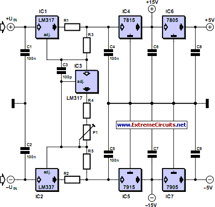
adjustable current limit for dual power
This current-limiting circuit, illustrated as part of a small bench power supply, can be utilized with any dual-rail current source. The section of the circuit on the left limits the current entering the dual voltage regulator (IC4 to IC7) to...

Current Limiting for Redundant Power Systems
The new TPS2359 hot-plug controller integrates all power management functions for two AdvancedMC (AMC) modules. Its current limiting circuitry enables designers to meet stringent AMC requirements, particularly in applications utilizing redundant supplies. A unique feature called multiswap maintains a fixed...
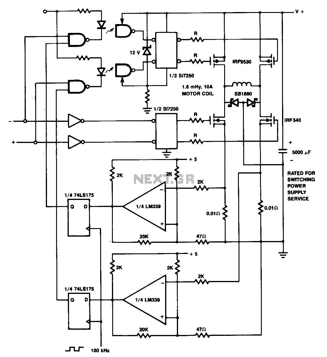
Practical-current-limiting-coil-driver
The p-channel devices are deactivated by current sensors when the coil current reaches 10 A. The operation resembles that of a switching-type power supply. Additionally, Schottky diodes and resistors are utilized for spike protection.
In this circuit, p-channel MOSFETs serve as...
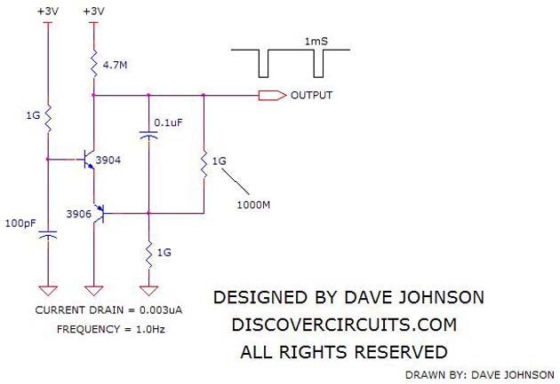
Ultra Low Current Oscillator
The circuit operates as a unijunction transistor relaxation oscillator. The base of the lower PNP transistor is biased at approximately half of the supply voltage. As the 100pF capacitor charges through the 1GΩ resistor, the base of the upper NPN...

pinouts
It is essential to implement current limiting when charging batteries. Open frame linear power supplies can be used for this purpose, with the current limit set to the recommended charging current of the battery. Foldback current limiting is particularly useful...

Simple current limiting circuit
When the current is below the specified threshold, the bias current supplied by resistor R1 causes transistor P3 to saturate and conduct. In this state, it is unable to regulate the current effectively. Conversely, when the current reaches or exceeds...