


CW117 CW217 CW317 12V constant-voltage charger
#constant voltage
#12V
#CW117
#CW217
#CW317
#power supply
#resistor
#voltage regulation
#charging circuit

Description: A 12V constant voltage charger is depicted. The power supply circuit shares the same basic design. The resistor R1, valued at 0.2 ohms, serves a limiting function, effectively increasing the internal resistance of the charger, which in turn reduces the charging rate. In the initial stage, the integrated voltage regulator functions as an overcurrent protection mechanism.
The 12V constant voltage charger circuit operates on the principle of maintaining a steady output voltage of 12 volts, regardless of variations in load or input voltage. The circuit typically consists of a transformer, rectifier, filter, and voltage regulator. The transformer steps down the AC voltage to a suitable level, while the rectifier converts the AC voltage to DC.
A smoothing capacitor follows the rectifier to filter out voltage ripples, providing a more stable DC output. The role of resistor R1, valued at 0.2 ohms, is crucial in limiting the charging current to prevent excessive current flow that could damage the battery or the charger itself. By increasing the internal resistance of the charger, R1 effectively slows down the charging process during the initial phase, allowing for a safer and more controlled charging environment.
The integrated voltage regulator plays a dual role in this circuit. Primarily, it ensures that the output voltage remains at a constant 12 volts, even when the input voltage fluctuates or when the load changes. Additionally, it provides overcurrent protection, which is essential for safeguarding both the charger and the connected battery. If the current exceeds a predetermined threshold, the voltage regulator will adjust its output to prevent damage, thereby enhancing the reliability and longevity of the charger.
Overall, this circuit design is essential for applications requiring a stable and reliable charging solution, such as in battery charging systems for various electronic devices. Proper selection of components, including the transformer, rectifier, and voltage regulator, along with careful consideration of resistor values, is critical for achieving optimal performance and safety in the charging process. As shown is a 12V constant voltage charger. The power supply circuit with the same basic circuit. Resistance Rl 0.2, limiting the role played, the equivalent of increasing the internal resistance of the charger can reduce the charging rate of charging the initial stage of the integrated voltage regulator plays the role of overcurrent protection.
The 12V constant voltage charger circuit operates on the principle of maintaining a steady output voltage of 12 volts, regardless of variations in load or input voltage. The circuit typically consists of a transformer, rectifier, filter, and voltage regulator. The transformer steps down the AC voltage to a suitable level, while the rectifier converts the AC voltage to DC.
A smoothing capacitor follows the rectifier to filter out voltage ripples, providing a more stable DC output. The role of resistor R1, valued at 0.2 ohms, is crucial in limiting the charging current to prevent excessive current flow that could damage the battery or the charger itself. By increasing the internal resistance of the charger, R1 effectively slows down the charging process during the initial phase, allowing for a safer and more controlled charging environment.
The integrated voltage regulator plays a dual role in this circuit. Primarily, it ensures that the output voltage remains at a constant 12 volts, even when the input voltage fluctuates or when the load changes. Additionally, it provides overcurrent protection, which is essential for safeguarding both the charger and the connected battery. If the current exceeds a predetermined threshold, the voltage regulator will adjust its output to prevent damage, thereby enhancing the reliability and longevity of the charger.
Overall, this circuit design is essential for applications requiring a stable and reliable charging solution, such as in battery charging systems for various electronic devices. Proper selection of components, including the transformer, rectifier, and voltage regulator, along with careful consideration of resistor values, is critical for achieving optimal performance and safety in the charging process. As shown is a 12V constant voltage charger. The power supply circuit with the same basic circuit. Resistance Rl 0.2, limiting the role played, the equivalent of increasing the internal resistance of the charger can reduce the charging rate of charging the initial stage of the integrated voltage regulator plays the role of overcurrent protection.

pull up and pull down resistor
Most beginners in digital electronics assume that a floating input represents a logic 0, which is a misconception. Floating inputs are in a neutral state and can represent either a logic 0 or a logic 1. This misunderstanding can lead...
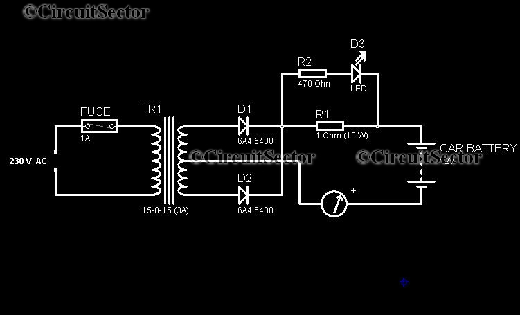
12V Low Cost Car Battery Charger Circuit PCB
In today's world, owning a car battery charger at home has become essential. Having one readily available can help prevent starting issues caused by battery problems. While purchasing a commercial battery charger can be expensive, the components required for constructing...

12V Auto-Powered Circuit For Cassette Recorders
A regulator enables the powering of a 7.5-V cassette recorder or other devices from a 12-V DC automotive system. The circuit can provide approximately 600 mA of current. Q3 requires a heatsink due to its potential to dissipate up to...

Evaluation Board For The Ad9834 Direct Digital Synthesizer
This document outlines the design of a low-cost 90 W flyback switching power supply intended for use in a multi-sync color monitor. To reduce screen interference caused by switching noise, the power supply can be automatically synchronized to the fixed...

Dragon -ZL-2801A DVD machine type switching power supply circuit
The Dragon ZL-2801A is a DVD machine that utilizes a switching power supply circuit. The circuit primarily consists of an AC input circuit, a rectifier filter wave circuit, an oscillation circuit switch, a switch transformer (Tl), a secondary rectifier, and...

Regulator circuit silicon resistor formed
The simple voltage regulator circuit consists of a silicon regulator and a resistor. It is designed to rectify and filter DC voltage, as illustrated in the accompanying figure. The voltage regulator is connected in parallel with the load, and the...
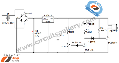
Simple battery charger circuit and battery level indicator with low battery recharge alarm
This is a straightforward 12V rechargeable smart battery charger circuit. It can be utilized as a charger for car batteries, inverter batteries, emergency light batteries, and more. An automatic indicator alarm circuit accompanies this battery charger schematic. The primary benefit...

Charging circuit from the DC power supply switching power supply control
Charging circuit from the DC power supply switching power supply control
The charging circuit described is designed to operate with a DC power supply, utilizing a switching power supply control mechanism. This type of circuit is commonly employed in applications where...

Remote tracking circuit schematics
The circuit consists of two main components: (1) a power supply circuit featuring a transformer (T) that steps down AC 220V to 33V, followed by a full-wave rectifier, a filter, and a three-terminal regulator that outputs +24V. This circuit also...