


GCA-60 silicon rectifier charging circuitry
#silicon rectifier
#three-phase bridge
#rectifier circuit
#voltage regulation
#charging circuitry
#TY regulator
#power electronics
#DC output
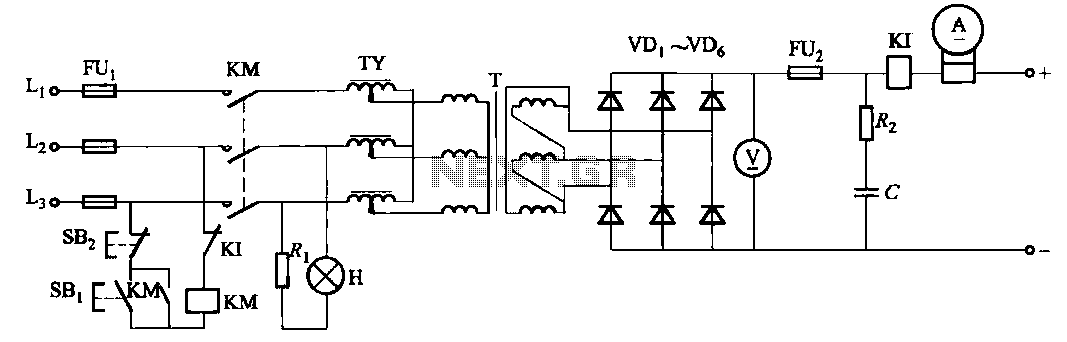
Description: There are a total of four types of specifications for a three-phase bridge rectifier circuit. The output voltage is regulated by a TY regulator.
The three-phase bridge rectifier circuit is designed to convert three-phase alternating current (AC) into direct current (DC). This circuit configuration consists of six diodes arranged in a bridge formation, allowing for efficient rectification of the three-phase input. The diodes are typically rated for high voltage and current to accommodate the demands of industrial applications.
In this circuit, the three-phase AC supply is connected to the anodes of the diodes, while the cathodes are connected together to form the positive output terminal. The negative output terminal is connected to the common point of the diodes. During each half-cycle of the AC waveform, two diodes conduct, allowing current to flow to the load. This results in a pulsating DC output, which can then be smoothed using filtering techniques.
The output voltage from the rectifier is further regulated by a TY regulator. The TY regulator is a voltage regulation device that ensures a stable output voltage despite variations in the input voltage or load conditions. It typically employs feedback control mechanisms to adjust the output voltage to a desired level, thus improving the overall performance and reliability of the power supply system.
The specifications of the circuit can vary based on the application requirements, such as the voltage and current ratings, as well as the type of load being driven. Overall, this configuration is essential for converting three-phase power into a usable DC form for various electronic and industrial applications.It is a total of four kinds of specifications. Three-phase bridge rectifier circuit. The output voltage from the regulator TY regulation.
The three-phase bridge rectifier circuit is designed to convert three-phase alternating current (AC) into direct current (DC). This circuit configuration consists of six diodes arranged in a bridge formation, allowing for efficient rectification of the three-phase input. The diodes are typically rated for high voltage and current to accommodate the demands of industrial applications.
In this circuit, the three-phase AC supply is connected to the anodes of the diodes, while the cathodes are connected together to form the positive output terminal. The negative output terminal is connected to the common point of the diodes. During each half-cycle of the AC waveform, two diodes conduct, allowing current to flow to the load. This results in a pulsating DC output, which can then be smoothed using filtering techniques.
The output voltage from the rectifier is further regulated by a TY regulator. The TY regulator is a voltage regulation device that ensures a stable output voltage despite variations in the input voltage or load conditions. It typically employs feedback control mechanisms to adjust the output voltage to a desired level, thus improving the overall performance and reliability of the power supply system.
The specifications of the circuit can vary based on the application requirements, such as the voltage and current ratings, as well as the type of load being driven. Overall, this configuration is essential for converting three-phase power into a usable DC form for various electronic and industrial applications.It is a total of four kinds of specifications. Three-phase bridge rectifier circuit. The output voltage from the regulator TY regulation.

Variable Voltage Regulation
Controlling the output voltage from a regulator can be made variable in three ways:
1. Using a fixed reference zener diode to increase the output by the value of the zener
2. A variable resistor for variable output, note that...

Variable Voltage and Current Power Supply circuit
An alternative approach to utilizing operational amplifiers (op-amps) for power supply regulation is presented. This method necessitates an additional winding on the power transformer to provide the op-amps with a bipolar voltage of +/- 8 volts. The negative voltage generated...

Regulator circuit silicon resistor formed
The simple voltage regulator circuit consists of a silicon regulator and a resistor. It is designed to rectify and filter DC voltage, as illustrated in the accompanying figure. The voltage regulator is connected in parallel with the load, and the...

Bridge voltage regulator circuit diagram using the
The circuit depicted in Figures A, B, and C demonstrates a high voltage coefficient. When the regulator resistance \( r_z \) is held constant, the bridge configuration achieves an infinite voltage coefficient. In Figure A, the load circuit is connected...
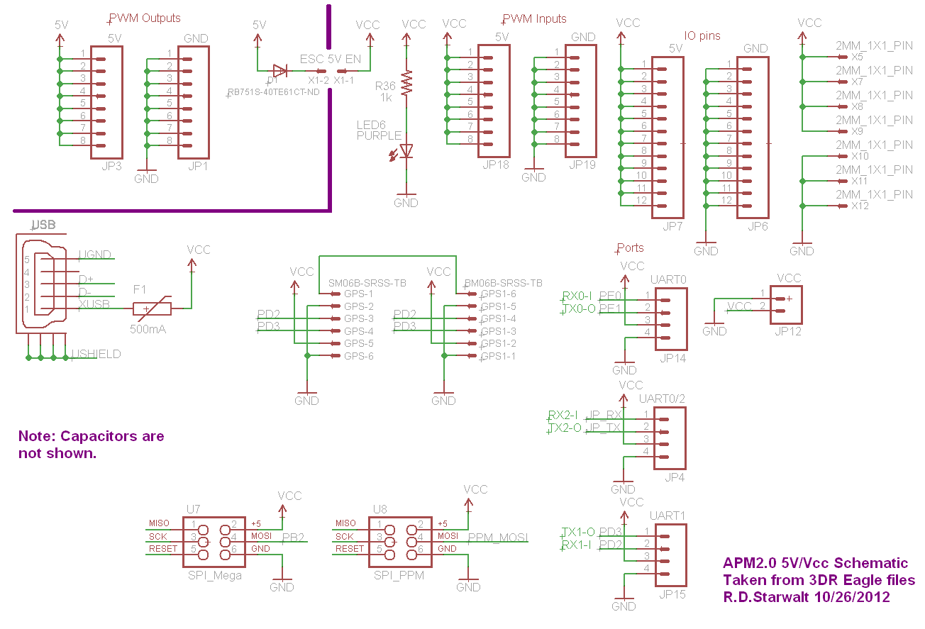
APM2.0 5V/Vcc Schematic
The PWM Output section has been separated into the upper left corner, delineated by a heavy purple line that is bridged by jumper JP1 on the APM2.0. This design choice highlights that diode D1 allows current to pass through JP1,...

variable voltage and current power supply
An alternative method for utilizing operational amplifiers (op-amps) to regulate a power supply is illustrated below. The power transformer necessitates an additional winding to provide the op-amps with a bipolar voltage of +/- 8 volts. This negative voltage is also...

Voltage Regulators
Until Willow Garage was acquired, there was work as a Web Robotics Engineer. This title reflects a role as a full-stack engineer focused on real-time, distributed robot control. Notable projects include an XML-RPC server and client for Node.js, a deprecated...

power Voltage supply clipping to <=3.3V
Supply it with a Li-Ion cell, which has a voltage range of 2.7 to 4.2V. The complexity of a buck/boost converter is not desired. While it is possible to regulate the voltage down to anything below 2.5V, it would be...

100v / 10ma regulator circuit
The circuit features no-load and short circuit protection mechanisms. To accommodate short circuit conditions, it is necessary to increase resistors R1 and R2 to allow for power dissipation; for example, R1 can be set to 1.2kΩ with a power rating...