


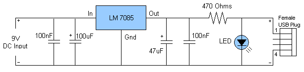
iPod charger Schematic

Description: This document serves as a supplementary guide to numerous existing resources that detail the construction of a USB charger. It is assumed that the reader possesses a basic understanding of electronics.
The construction of a USB charger typically involves a few essential components: a power source, a voltage regulator, and USB output connectors. The power source can be a battery or an AC to DC adapter, which provides the necessary voltage and current to charge devices.
A common voltage regulator used in USB chargers is the LM7805, which steps down higher voltages to a stable 5V output suitable for USB devices. The input voltage range for the LM7805 is typically between 7V to 35V, allowing it to accommodate various power sources.
To design a basic USB charger circuit, the following components are required:
1. **Power Source**: An AC to DC adapter rated at 5V or higher (depending on the regulator used).
2. **Voltage Regulator**: An LM7805 or similar linear regulator.
3. **Capacitors**: Input and output capacitors (usually 0.33µF and 0.1µF respectively) are recommended to stabilize the voltage and reduce noise.
4. **USB Connector**: A standard USB Type-A or Type-B connector for output.
5. **Protection Diodes**: To prevent reverse polarity and protect the circuit from potential damage.
The circuit can be assembled on a breadboard for prototyping or soldered onto a PCB for a more permanent solution. The connections should be made as follows:
- Connect the input of the voltage regulator to the positive terminal of the power source.
- Connect the ground of the power source to the ground of the voltage regulator.
- Attach the output of the voltage regulator to the VBUS pin of the USB connector.
- Connect the ground of the USB connector to the common ground.
Testing the circuit involves measuring the output voltage with a multimeter to ensure it is stable at 5V. Once verified, the charger can be used to charge compatible USB devices safely. Proper heat dissipation methods should be considered, especially if the charger will be used for extended periods or with high current loads.First off I should mention that this is supplemental Instructable to the countless others that show you how to build a USB charger. I am assuming you..
The construction of a USB charger typically involves a few essential components: a power source, a voltage regulator, and USB output connectors. The power source can be a battery or an AC to DC adapter, which provides the necessary voltage and current to charge devices.
A common voltage regulator used in USB chargers is the LM7805, which steps down higher voltages to a stable 5V output suitable for USB devices. The input voltage range for the LM7805 is typically between 7V to 35V, allowing it to accommodate various power sources.
To design a basic USB charger circuit, the following components are required:
1. **Power Source**: An AC to DC adapter rated at 5V or higher (depending on the regulator used).
2. **Voltage Regulator**: An LM7805 or similar linear regulator.
3. **Capacitors**: Input and output capacitors (usually 0.33µF and 0.1µF respectively) are recommended to stabilize the voltage and reduce noise.
4. **USB Connector**: A standard USB Type-A or Type-B connector for output.
5. **Protection Diodes**: To prevent reverse polarity and protect the circuit from potential damage.
The circuit can be assembled on a breadboard for prototyping or soldered onto a PCB for a more permanent solution. The connections should be made as follows:
- Connect the input of the voltage regulator to the positive terminal of the power source.
- Connect the ground of the power source to the ground of the voltage regulator.
- Attach the output of the voltage regulator to the VBUS pin of the USB connector.
- Connect the ground of the USB connector to the common ground.
Testing the circuit involves measuring the output voltage with a multimeter to ensure it is stable at 5V. Once verified, the charger can be used to charge compatible USB devices safely. Proper heat dissipation methods should be considered, especially if the charger will be used for extended periods or with high current loads.First off I should mention that this is supplemental Instructable to the countless others that show you how to build a USB charger. I am assuming you..

Sanyo 83P switching power supply circuit diagram
Oscillation: The positive terminal voltage of C310 is approximately 300V. The resistors R311 and R312 are connected to the switch BG311 at the B pole, while the B301 winding via the switching transformer (4) and (6) is connected to the...

250 Watt PC power Supply
Up to 10 A continuous output current, or operation with 50 % ESD and 18 A peak current are possible without a fan if sufficient natural air flow is present and the ambient temperature does not exceed 30 °C. A...

Industrial fuel oil furnace controller circuit diagram 2
The industrial fuel oil furnace controller circuit consists of a power supply circuit, a testing and ignition control circuit, and a control implementation circuit, as illustrated in the accompanying diagram. The power supply circuit includes a step-down capacitor (C6), a...

Batteries charger & PSU - ideal for digital camerass
This circuit was designed for digital cameras, which are known to have significant power consumption. For instance, the Minolta E223 camera requires approximately 800 mA. In practice, this demand can be met using a mains power supply or high-capacity NiMH...

Charging circuit diagram personal work
Charging circuit diagram for personal work based on the operating principle of ADP3801/3802 charging circuit.
The ADP3801/3802 is a highly integrated battery charger controller designed for Li-ion and Li-polymer batteries. The charging circuit typically consists of several key components including the...

Low-Power Car/Bike USB Charger
An efficient USB charger designed to operate from a 12V car battery, achieving up to 89% efficiency and capable of charging USB devices at currents up to 525mA. It does not drain the battery if left permanently connected, provided the...
usb charger
A portable battery-powered USB charger circuit or schematic utilizing the IC LM7805. The circuit requires only a few components.
The portable battery-powered USB charger circuit based on the LM7805 voltage regulator is designed to convert a higher voltage from a battery...

switching power supply schematic
This post summarizes the work of experts in switching power supply schematic diagrams who are thoroughly knowledgeable about all aspects of the subject.
Switching power supplies are crucial components in modern electronic devices, providing efficient voltage regulation and power conversion. The...

markII
The following circuits are presented in a logical order from initial power-up to the additional features incorporated at the end of the project. A less organized version of the Mark II design exists, but this is the sanitized and organized...