


Low-battery-protector-
#low-battery
#battery protection
#voltage detector
#Schottky diode
#trickle charge
#low-current
#switch
#battery backup
#over-discharge

Description: To prevent battery damage due to over-discharge, a low-voltage detector and switch should be included in the design of the battery backup circuit. The detector circuit should consume extremely low current. The switch should exhibit a low-voltage drop and be easy to control. R1 and D2 provide a trickle charge for the battery. Chosen for its low forward voltage drop, Schottky diode D3 prevents forward polarization of the diode incorporated in Q1. When the battery voltage is above approximately 8 V, the output of U1 is low and Q1 is turned on. If the battery voltage falls below 8 V, the output of U1 increases and turns off Q1.
In the proposed battery backup circuit, a low-voltage detection mechanism is critical to safeguard against over-discharge conditions that could lead to battery damage. The circuit incorporates a low-voltage detector that operates with minimal current draw, ensuring that the overall power consumption remains low, which is essential for battery-operated applications.
The low-voltage switch is designed to maintain a low-voltage drop, facilitating efficient operation. Resistor R1 and diode D2 are included in the circuit to provide a trickle charge to the battery, ensuring that it remains charged during periods of inactivity. The use of a Schottky diode, specifically D3, is advantageous due to its low forward voltage drop, which minimizes power loss and enhances efficiency. This diode also plays a critical role in preventing reverse bias conditions that could adversely affect the performance of transistor Q1.
The operational behavior of the circuit is defined by the voltage levels present at the battery. When the battery voltage is maintained above approximately 8 V, the output from operational amplifier U1 remains low, which keeps transistor Q1 in the 'on' state, allowing current to flow and the battery to be utilized effectively. Conversely, when the battery voltage drops below the 8 V threshold, the output of U1 transitions to a high state, which turns off Q1, thereby disconnecting the load and preventing further discharge of the battery. This design not only protects the battery from over-discharge but also enhances the longevity and reliability of the power source in the application.To prevent battery damage due to over -disc barge, a low-voltage detector and switch should be included in the design of the battery backup circuit. The detector circuit should consume extremely low current. The switch should exlnbit a low-voltage drop and be easy to control. R1 and D2 provide a trickle charge for the battery. Chosen for its low forward voltage drop, Schottky diode D3 prevents forward polarization of the diode incorporated in Ql.
When the battery voltage is above approximately 8 V, the output of U1 is low and Ql is turned on. If the battery voltage falls below 8 V, the output of U1 increases and turns off Ql.
In the proposed battery backup circuit, a low-voltage detection mechanism is critical to safeguard against over-discharge conditions that could lead to battery damage. The circuit incorporates a low-voltage detector that operates with minimal current draw, ensuring that the overall power consumption remains low, which is essential for battery-operated applications.
The low-voltage switch is designed to maintain a low-voltage drop, facilitating efficient operation. Resistor R1 and diode D2 are included in the circuit to provide a trickle charge to the battery, ensuring that it remains charged during periods of inactivity. The use of a Schottky diode, specifically D3, is advantageous due to its low forward voltage drop, which minimizes power loss and enhances efficiency. This diode also plays a critical role in preventing reverse bias conditions that could adversely affect the performance of transistor Q1.
The operational behavior of the circuit is defined by the voltage levels present at the battery. When the battery voltage is maintained above approximately 8 V, the output from operational amplifier U1 remains low, which keeps transistor Q1 in the 'on' state, allowing current to flow and the battery to be utilized effectively. Conversely, when the battery voltage drops below the 8 V threshold, the output of U1 transitions to a high state, which turns off Q1, thereby disconnecting the load and preventing further discharge of the battery. This design not only protects the battery from over-discharge but also enhances the longevity and reliability of the power source in the application.To prevent battery damage due to over -disc barge, a low-voltage detector and switch should be included in the design of the battery backup circuit. The detector circuit should consume extremely low current. The switch should exlnbit a low-voltage drop and be easy to control. R1 and D2 provide a trickle charge for the battery. Chosen for its low forward voltage drop, Schottky diode D3 prevents forward polarization of the diode incorporated in Ql.
When the battery voltage is above approximately 8 V, the output of U1 is low and Ql is turned on. If the battery voltage falls below 8 V, the output of U1 increases and turns off Ql.

Intelligent trailing switch
This circuit is a straightforward yet effective design where devices connected to the trailing sockets will operate only when the device connected to the control socket is powered on. For instance, if a motor is connected to the control socket...

How To Build A Simple Code-Operated Switch
This is a simplified version of the Universal Keypad-Operated Switch. The design has been modified to reduce circuit complexity and the number of components required, resulting in somewhat less secure code functionality. However, it remains adequate for many applications. The...

Schiepatti Switch
A highly versatile switch that can be controlled from any channel on a typical Futaba or JR radio setup. This switch was designed to trigger the shutter on digital cameras without the need for a servo attached to the camera....

under?-over voltage detector
In Fig. 1 A precision DC undervoltage relay switch. The op-amp is wired as a voltage comparator, with a reference voltage applied to pin 2 and the test voltage applied to pin 3: the relay turns on when the pin...

battery backup circuit
A two-diode selector circuit is utilized when the primary voltage source exceeds both the diodes' turn-on voltage and the input voltage of the second diode. Schottky diodes are preferred due to their low turn-on voltage (typically 0.4V) and high switching...

2 Way Switch Wire Electrical
The following circuit illustrates a 2-way switch wiring electrical circuit diagram. Features include the ability to turn on the lights using switch S1, which has three terminals.
The 2-way switch circuit is commonly used in residential and commercial applications to control...

Voltage detector relay
While the battery is charging, its voltage is measured at V. If the measured voltage is lower than the minimum threshold, the relay will be activated, connecting the charger circuit. When the battery voltage exceeds the maximum set point, the...

Battery Backups in Consumer Electronics
Most individuals are unaware that there are typically over a dozen battery backup systems present in their homes. The average American has around 18 battery-backed devices in their household. These battery backup systems protect crucial, expensive, or portable electronics that...
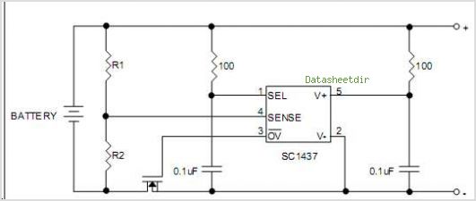
SC1437 Precision Voltage Detector With Programmable Trigger Voltage & Timer Delay - Semtech Corporation
The SC9256 is a phase-locked loop (PLL) integrated circuit designed for digital tuning systems (DTS), featuring built-in 2 modulus prescalers. All functions are controlled through three serial bus lines. These integrated circuits are utilized to configure high-performance digital tuning systems....