


Low-voltage-indicator
#low-voltage
#indicator
#transistor
#SCR
#potentiometer
#bias voltage
#monitoring
#circuit protection

Description: The input terminal VIN is connected to the +V line of the circuit that the indicator is meant to monitor, and the grounds of both circuits are interconnected. The position of the potentiometer R1's wiper determines the base voltage of transistor Q1. As long as the transistor receives sufficient bias voltage to remain on, the low voltage at the collector will prevent the SCR from firing. As the battery voltage begins to decrease, the base voltage of the transistor will also decline. When Q1 turns off (as VIN drops), the collector voltage rises. This increase in voltage provides enough gate drive to activate the SCR, which in turn illuminates the LED. The LED can also be replaced with a buzzer or any other type of warning device.
The circuit described functions as a voltage monitoring system utilizing a transistor (Q1) and a silicon-controlled rectifier (SCR) to indicate when the voltage level drops below a predefined threshold. The input terminal VIN serves as the voltage reference point, linked directly to the monitored circuit's positive voltage line. The common ground connection ensures a stable reference point for both the monitoring circuit and the indicator.
The potentiometer R1 plays a crucial role in setting the bias voltage for the transistor Q1. By adjusting the wiper of R1, the user can fine-tune the base voltage applied to Q1, thus controlling its operation. When the battery voltage is adequate, Q1 remains in the 'on' state, allowing low voltage at its collector. This low collector voltage inhibits the SCR from conducting, preventing the LED (or alternative warning device) from activating.
As the battery voltage begins to decline, the base voltage of Q1 also decreases due to the voltage divider effect created by R1. Once the base voltage falls below a certain threshold, Q1 turns off, leading to a rise in the collector voltage. This increase is critical as it provides the necessary gate trigger for the SCR to turn on, resulting in the activation of the LED or other warning mechanisms.
The design allows for flexibility in the choice of the warning device. While the LED is commonly used for visual indication, a buzzer can be employed for audible alerts, enhancing the circuit's functionality in various applications. This monitoring circuit is particularly useful in battery-operated devices where maintaining a certain voltage level is essential for proper operation.Input terminal VIN is connected to the +V line of tbe circuit that the indicator is to monitor, and the grounds of botb circuits are connected togetber. The position of potentiometer Rl"s wiper determines Q1"s base voltage. As long as the transistor gets enough bias voltage to remain on, the low voltage at tbe collector will keep the SCR from firing.
As tbe battery voltage starts to fall, the transistor"s base voltage will fall as well. When Ql turns off (VIN drops), tbe collector voltage increases. That voltage provides enough gate drive to tum on the SCR, which turns on tbe LED. The LED could also be a buzzer or almost any otber type of warning device.
The circuit described functions as a voltage monitoring system utilizing a transistor (Q1) and a silicon-controlled rectifier (SCR) to indicate when the voltage level drops below a predefined threshold. The input terminal VIN serves as the voltage reference point, linked directly to the monitored circuit's positive voltage line. The common ground connection ensures a stable reference point for both the monitoring circuit and the indicator.
The potentiometer R1 plays a crucial role in setting the bias voltage for the transistor Q1. By adjusting the wiper of R1, the user can fine-tune the base voltage applied to Q1, thus controlling its operation. When the battery voltage is adequate, Q1 remains in the 'on' state, allowing low voltage at its collector. This low collector voltage inhibits the SCR from conducting, preventing the LED (or alternative warning device) from activating.
As the battery voltage begins to decline, the base voltage of Q1 also decreases due to the voltage divider effect created by R1. Once the base voltage falls below a certain threshold, Q1 turns off, leading to a rise in the collector voltage. This increase is critical as it provides the necessary gate trigger for the SCR to turn on, resulting in the activation of the LED or other warning mechanisms.
The design allows for flexibility in the choice of the warning device. While the LED is commonly used for visual indication, a buzzer can be employed for audible alerts, enhancing the circuit's functionality in various applications. This monitoring circuit is particularly useful in battery-operated devices where maintaining a certain voltage level is essential for proper operation.Input terminal VIN is connected to the +V line of tbe circuit that the indicator is to monitor, and the grounds of botb circuits are connected togetber. The position of potentiometer Rl"s wiper determines Q1"s base voltage. As long as the transistor gets enough bias voltage to remain on, the low voltage at tbe collector will keep the SCR from firing.
As tbe battery voltage starts to fall, the transistor"s base voltage will fall as well. When Ql turns off (VIN drops), tbe collector voltage increases. That voltage provides enough gate drive to tum on the SCR, which turns on tbe LED. The LED could also be a buzzer or almost any otber type of warning device.

Motor time division control circuit composed of transistor and NE555
Figure 2-32 (a) illustrates the time control diagram for a motor operated by switch S1. When S1 is set to position 1, the power driver circuit supplies current to the motor, enabling it to run. When S1 is switched to...

Two-Transistor DC Motor DriverCircuit Using The TIP32 Transistor
The following circuit illustrates a two-transistor DC motor driver circuit diagram. This circuit utilizes the TIP32 transistor. Features: operates in...
The two-transistor DC motor driver circuit is designed to control the operation of a DC motor using two NPN transistors, which...

Two Transistor (Boys Radio) Schematic and Theory of Operation
An analysis of certain radios reveals the impressive engineering by Japanese designers, particularly in creating a radio capable of driving a speaker with only two transistors. The first transistor (Q1) serves a dual function; it operates as an RF amplifier...
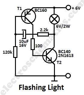
Flashing Light Circuit with Transistors
This simple flashing light circuit operates at 6 volts and 0.5A, exhibiting low current consumption when the light bulb is turned off. The frequency of the flashing is predetermined.
The circuit consists of a power supply, typically a battery or a...

DARLINGTON LOGIC PROBE
A two-transistor Darlington connection offers a very high input impedance, ensuring that it does not load the logic circuit being monitored. This configuration drives an LED that illuminates when a logic high (1) is present at the input.
The two-transistor Darlington...

Free-Electron Pump (FEP) Experiments
A simple two-transistor inverter circuit has been constructed for this experiment. The transformer depicted is the inverter transformer. The output voltage from the inverter is in the form of pulses, with an estimated peak value of approximately 700V. When a...

Transistor amplifier circuits
Transistor amplifier circuits that are simple and easy to construct. This includes a headphone amplifier, a four-transistor amplifier, and a low-power amplifier.
Transistor amplifier circuits are fundamental components in electronic design, offering various applications ranging from audio amplification to signal processing....

An SCR Based Burglar Alarm
This is a simple SCR-based burglar alarm circuit. Its features include automatic exit and entry delays, along with a timed bell cut-off and reset. It is designed to be used with standard types of normally-closed input devices such as magnetic...

Low-voltage oscillator features increased spectral purity
A common issue in crystal sinusoidal oscillators is the excitation of unintended modes of the quartz crystal, which diminishes the spectral purity of the oscillator. This issue is particularly significant in overtone crystals, especially for low-voltage applications. In such cases,...