


Ni-Cd Battery Automatic Charger
#Ni-Cd
#automatic charger
#LM311
#comparator
#transistor
#LED indicator
#AAA batteries
#voltage monitoring
#charging control

Description: The circuit presented in the above schematic has been designed to charge automatically two series 350mAh "AAA" size batteries. Set the 20KOhms multiturn potentiometer to get a 2.78V on the 3rd pin of the LM311 which is a comparator. So if the net voltage of batteries reaches at 2.81V, the output of the LM311 goes high and then the state of the transistor becomes off, resulting in charging operation stops. When the red LED is lighted, it indicates that the charging is in the progress, and vice versa. More: To use portable devices such as digital camera, wireless headphone, pocket radio, etc, which they operates with two "AAA" size batteries, using rechargeable Ni-Cd batteries is a conscionable way to reduce cost.
The circuit operates by utilizing an LM311 voltage comparator to monitor the charge state of two 350mAh "AAA" Ni-Cd batteries connected in series. The design includes a 20K Ohm multiturn potentiometer that allows for precise adjustment of the reference voltage at the third pin of the LM311. This reference voltage is set to 2.78V, which is critical for determining the charging threshold.
When the combined voltage of the two batteries reaches 2.81V, the output of the LM311 transitions to a high state. This transition is used to control a transistor that interrupts the charging current to the batteries, effectively stopping the charging process to prevent overcharging. The inclusion of a red LED serves as a visual indicator of the charging state; it illuminates when the batteries are being charged and turns off when the charging process has completed.
This circuit design is particularly advantageous for powering portable devices such as digital cameras, wireless headphones, and pocket radios, which typically require two "AAA" batteries. By employing rechargeable Ni-Cd batteries, users can significantly reduce operational costs and contribute to environmental sustainability through reduced battery waste. The automatic charging feature ensures that the batteries are charged efficiently and safely, enhancing the usability and longevity of the devices powered by this setup.The circuit presented in the above schematic has been designed to charge automatically two series 350mAh "AAA" size batteries. Set the 20KOhms multiturn potentiometer to get a 2.78V on the 3rd pin of the LM311 which is a comparator.
So if the net voltage of batteries reaches at 2.81V, the output of the LM311 goes high and then the state of the transistor becomes off, resulting in charging operation stops. When the red LED is lighted, it indicates that the charging is in the progress, and vice versa. To use portable devices such as digital camera, wireless headphone, pocket radio, etc, which they operates with two "AAA" size batteries, using rechargeable Ni-Cd batteries is a conscionable way to reduce cost.
The circuit operates by utilizing an LM311 voltage comparator to monitor the charge state of two 350mAh "AAA" Ni-Cd batteries connected in series. The design includes a 20K Ohm multiturn potentiometer that allows for precise adjustment of the reference voltage at the third pin of the LM311. This reference voltage is set to 2.78V, which is critical for determining the charging threshold.
When the combined voltage of the two batteries reaches 2.81V, the output of the LM311 transitions to a high state. This transition is used to control a transistor that interrupts the charging current to the batteries, effectively stopping the charging process to prevent overcharging. The inclusion of a red LED serves as a visual indicator of the charging state; it illuminates when the batteries are being charged and turns off when the charging process has completed.
This circuit design is particularly advantageous for powering portable devices such as digital cameras, wireless headphones, and pocket radios, which typically require two "AAA" batteries. By employing rechargeable Ni-Cd batteries, users can significantly reduce operational costs and contribute to environmental sustainability through reduced battery waste. The automatic charging feature ensures that the batteries are charged efficiently and safely, enhancing the usability and longevity of the devices powered by this setup.The circuit presented in the above schematic has been designed to charge automatically two series 350mAh "AAA" size batteries. Set the 20KOhms multiturn potentiometer to get a 2.78V on the 3rd pin of the LM311 which is a comparator.
So if the net voltage of batteries reaches at 2.81V, the output of the LM311 goes high and then the state of the transistor becomes off, resulting in charging operation stops. When the red LED is lighted, it indicates that the charging is in the progress, and vice versa. To use portable devices such as digital camera, wireless headphone, pocket radio, etc, which they operates with two "AAA" size batteries, using rechargeable Ni-Cd batteries is a conscionable way to reduce cost.
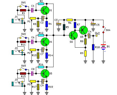
3 channel Transistor Audio Mixer
The 3-channel audio mixer is a compact application utilizing transistor amplifiers. This audio mixer operates with a supply voltage of 9V DC, which can be provided by a battery. It is designed specifically for use as a portable amplifier. The...

Dynamic Microphone Preamplifier using C945 transistor
This circuit utilizes three transistors (2SC945, 2C1815, or 2SC828) as the primary components, functioning as a typical low-noise transistor amplifier. It offers a gain of approximately 200 to 300 times and has a frequency response ranging from 50Hz to 100KHz....

easy build motocycle alarm
The circuit requires two transistors to drive a relay, which acts as a switch to activate a buzzer. Any number of normally-open switches may be applied. Mercury switches should be installed to ensure they close when the steering is engaged....

microcontroller Why this transistor logic as switch is not working
The remote control of an RC car was modified by extending wires from the backward, forward, left, and right switches. Grounding any of these wires completes the circuit and sends a signal to the car. The intention is to close...

Ni-Cd battery charger circuit
This circuit is primarily designed for charging 12V Ni-Cd battery packs. However, it can also be used to charge 6V and 9V battery packs with slight modifications.
The circuit operates by utilizing a power supply that provides the necessary voltage and...

Transistor LED flasher
The circuits discussed here are simple LED flashers that typically illuminate one or two LEDs, contrasting with more complex light chaser circuits that can flash four or more. While the most basic option is a flashing LED, it lacks control...
Null-detector
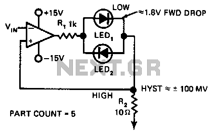
In this indicating comparator circuit, R2 sets the hysteresis. If the 741 saturates at ±12 V, the current in R1 will be approximately ±10 mA if a 0.1 V hysteresis is desired. More: Then 0.1 V/10 mA ~ 100.
The indicating...

Simple Metronome With Transistors
A flip-flop, functioning as an astable multivibrator, can be utilized to generate timing signals in music applications such as a metronome. This can be achieved by adjusting the transistor bias resistor with a value of 100k.
The astable multivibrator configuration of...

Data Switch with LED
Just to prove that transistors can also be useful in logic situations; this is a data latch and indicator which also is a data switch and has a bidirectional input/output port which can be read or switched. If the second...