


Ni-Cd Battery Charger Super Fast Circuit
#Ni-Cd battery
#MAX 712
#fast charging
#300mA
#battery management
#charging circuit
#IC based
#energy
#power supply
#electronics

Description: The following circuit illustrates a super fast Ni-Cd battery charger. It is based on the IC MAX 712 and is designed to charge a Ni-Cd battery at a rate of 300 mA.
The circuit utilizes the MAX 712 integrated circuit, which is specifically designed for charging Ni-Cd batteries efficiently. The MAX 712 features a precision voltage regulation system that ensures optimal charging of the batteries while preventing overcharging, which can lead to battery damage. The charging current of 300 mA is suitable for standard Ni-Cd batteries, allowing for a rapid charge cycle while maintaining battery health.
The circuit typically includes additional components such as resistors, capacitors, and diodes to support the functionality of the MAX 712. The input voltage is usually supplied from a transformer or a wall adapter, which is then rectified and filtered to provide a stable DC voltage to the charging circuit.
The MAX 712 monitors the battery voltage and adjusts the charging current accordingly, ensuring that the battery is charged to its full capacity without exceeding safe voltage limits. Furthermore, a temperature sensor may be integrated into the circuit to provide additional protection by interrupting the charging process if the battery temperature exceeds a predetermined threshold.
For practical implementation, it is essential to follow the manufacturer's guidelines for component selection and PCB layout to minimize noise and interference, which can affect charging efficiency. Overall, this circuit design offers a robust solution for fast charging of Ni-Cd batteries, making it suitable for various applications where quick battery turnaround is necessary.The following circuit shows about Ni-Cd Battery Charger Super Fast Circuit. Features: based on the IC MAX 712, Ni-Cd battery at 3oomA, charging ..
The circuit utilizes the MAX 712 integrated circuit, which is specifically designed for charging Ni-Cd batteries efficiently. The MAX 712 features a precision voltage regulation system that ensures optimal charging of the batteries while preventing overcharging, which can lead to battery damage. The charging current of 300 mA is suitable for standard Ni-Cd batteries, allowing for a rapid charge cycle while maintaining battery health.
The circuit typically includes additional components such as resistors, capacitors, and diodes to support the functionality of the MAX 712. The input voltage is usually supplied from a transformer or a wall adapter, which is then rectified and filtered to provide a stable DC voltage to the charging circuit.
The MAX 712 monitors the battery voltage and adjusts the charging current accordingly, ensuring that the battery is charged to its full capacity without exceeding safe voltage limits. Furthermore, a temperature sensor may be integrated into the circuit to provide additional protection by interrupting the charging process if the battery temperature exceeds a predetermined threshold.
For practical implementation, it is essential to follow the manufacturer's guidelines for component selection and PCB layout to minimize noise and interference, which can affect charging efficiency. Overall, this circuit design offers a robust solution for fast charging of Ni-Cd batteries, making it suitable for various applications where quick battery turnaround is necessary.The following circuit shows about Ni-Cd Battery Charger Super Fast Circuit. Features: based on the IC MAX 712, Ni-Cd battery at 3oomA, charging ..

250 Watt PC power Supply
Up to 10 A continuous output current, or operation with 50 % ESD and 18 A peak current are possible without a fan if sufficient natural air flow is present and the ambient temperature does not exceed 30 °C. A...

Power Supply for P.A. Class40
For its maximum result, the final stage of the amplifier should have the proper power supply, as the flowing currents are very high. A Class A amplifier requires attention. These are the rules for the power supply for the Class...

Charging circuit diagram personal work
Charging circuit diagram for personal work based on the operating principle of ADP3801/3802 charging circuit.
The ADP3801/3802 is a highly integrated battery charger controller designed for Li-ion and Li-polymer batteries. The charging circuit typically consists of several key components including the...
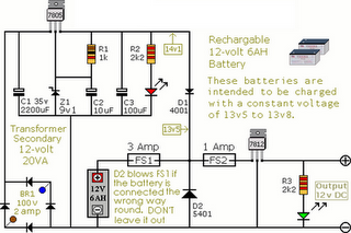
Circuit Diagram Of Alarm Power Supply
The following circuit illustrates an Alarm Power Supply Circuit Diagram. Features include a 1-amp current output, suitable for a Modular Burglar Alarm operating at 12 volts.
The Alarm Power Supply Circuit is designed to provide a stable and reliable power source...
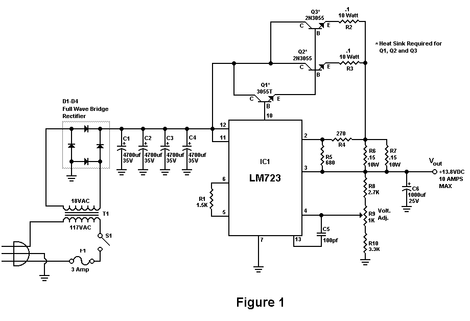
Build A 10 Amp 13.8 Volt Power Supply
Sometimes amateurs like to home-brew their power supplies instead of purchasing one off the shelf at any of the major ham radio retail dealers. The advantage to rolling your own power supply is that it teaches us how they work...

Electronics Projects Circuits
Over 1400 top electronics projects and electronic circuits with photos, datasheets, and easy-to-read schematics, along with explanations of how they work and how to build them.
The collection comprises a vast array of electronics projects suitable for enthusiasts and professionals alike....

Lighting controller circuit
The circuit operates with a controller that includes a power supply circuit, a control circuit, and an audio amplifier, which are three distinct components. The power circuit comprises diodes VD1 to VD4, resistor R1, capacitor C1, LED1, LED2, and additional...

Power Supply Monitor /Memory Protector
This circuit detects low-voltage supply conditions, down to 0.6 V. Diode D1 sets the trip point of the circuit. The circuit is useful for protecting memory circuits from accidental writes during low-voltage power supply conditions, which can cause other circuits...

faster charger circuit 6-12 volt
This circuit is designed for rapid battery charging. It is recommended for those who require a faster charger. The charger operates at a low temperature of 5 degrees Celsius. The input voltage is 15 volts DC, while the output voltage...