


NiCads charger
#NiCads
#charger
#voltage reference
#LM385BZ-2.5
#current booster
#integrator
#foldover
#driver circuit

Description: The driver circuit has 4 main sections:
* the voltage definition,
* the integrator,
* the current booster, and
* the foldover. The schematic is drawn so that higher voltages are toward the top and lower voltages are towards the bottom. D1 is a voltage reference, LM385BZ-2.5, that maintains a drop of 2.5 volts across its leads. Since B will be close to ground, there should be about 1.5 volts across R1 and about 0.8 mA of current, which is enough to keep D1 alive. The schematic above shows the overall control loop. The glowplug is represented by R9. Notice there are 2 connections at each end of the plug. The heavy lines represent heavy wire that carries the current to/from the plug. The thinner
The driver circuit is designed to control the operation of a glowplug, which is a resistive heating element used in diesel engines to aid cold starting. The circuit is divided into four distinct sections that each serve a specific function in the overall operation.
The voltage definition section utilizes the LM385BZ-2.5 voltage reference diode (D1), which ensures a stable 2.5V reference voltage necessary for the proper functioning of the circuit. This voltage reference is critical as it sets the baseline for the other components in the circuit. The resistor R1 is connected in series with the voltage reference to limit the current flowing through D1, ensuring that it operates within its specified range. The expected voltage drop across R1 is approximately 1.5V, leading to a current of around 0.8 mA, which is sufficient to maintain the operation of the voltage reference.
The integrator section processes the input signal and provides necessary feedback to maintain the desired operating conditions for the glowplug. This section typically includes an operational amplifier configured to integrate the voltage over time, ensuring that the output is a smooth, continuous signal rather than a pulsed one.
The current booster section is responsible for amplifying the current supplied to the glowplug. Given that the glowplug requires a significant amount of current to reach its operating temperature, this section is designed to handle higher currents without overheating or failing. It may include transistors or MOSFETs configured to switch larger currents while being controlled by the lower current signals from the previous sections.
Lastly, the foldover section serves as a protection mechanism, preventing the circuit from exceeding safe operational limits. It monitors the output current and voltage, ensuring that they remain within specified thresholds. If the current approaches unsafe levels, the foldover circuit will reduce the output, protecting both the glowplug and the driver circuit from damage.
The overall schematic is organized with higher voltage connections at the top and lower voltage connections at the bottom, which aids in understanding the flow of current through the circuit. The glowplug, represented by R9, is connected via heavy gauge wires, indicated by the thick lines in the schematic, to handle the significant current required for operation. The thinner lines represent other connections that may carry lower currents or signals. The careful design and arrangement of these components ensure the effective and safe operation of the glowplug driver circuit.The driver circuit (see the complete schematic) has 4 main sections: * the voltage definition, * the integrator, * the current booster, and * the foldover. The schematic is drawn so that higher voltages are toward the top and lower voltages are towards the bottom.
D1 is a voltage reference, LM385BZ-2.5 (you can get all these parts from Allied Electronics), that maintains a drop of 2.5 volts across its leads. Since B will be close to ground, there should be about 1.5 volts across R1 and about 0.8 mA of current, which is enough to keep D1 alive.
The (somewhat abstract) schematic above shows the overall control loop. The glowplug is represented by R9. Notice there are 2 connections at each end of the plug. The heavy lines represent heavy wire that carries the current to/from the plug. The thinner
* the voltage definition,
* the integrator,
* the current booster, and
* the foldover. The schematic is drawn so that higher voltages are toward the top and lower voltages are towards the bottom. D1 is a voltage reference, LM385BZ-2.5, that maintains a drop of 2.5 volts across its leads. Since B will be close to ground, there should be about 1.5 volts across R1 and about 0.8 mA of current, which is enough to keep D1 alive. The schematic above shows the overall control loop. The glowplug is represented by R9. Notice there are 2 connections at each end of the plug. The heavy lines represent heavy wire that carries the current to/from the plug. The thinner
The driver circuit is designed to control the operation of a glowplug, which is a resistive heating element used in diesel engines to aid cold starting. The circuit is divided into four distinct sections that each serve a specific function in the overall operation.
The voltage definition section utilizes the LM385BZ-2.5 voltage reference diode (D1), which ensures a stable 2.5V reference voltage necessary for the proper functioning of the circuit. This voltage reference is critical as it sets the baseline for the other components in the circuit. The resistor R1 is connected in series with the voltage reference to limit the current flowing through D1, ensuring that it operates within its specified range. The expected voltage drop across R1 is approximately 1.5V, leading to a current of around 0.8 mA, which is sufficient to maintain the operation of the voltage reference.
The integrator section processes the input signal and provides necessary feedback to maintain the desired operating conditions for the glowplug. This section typically includes an operational amplifier configured to integrate the voltage over time, ensuring that the output is a smooth, continuous signal rather than a pulsed one.
The current booster section is responsible for amplifying the current supplied to the glowplug. Given that the glowplug requires a significant amount of current to reach its operating temperature, this section is designed to handle higher currents without overheating or failing. It may include transistors or MOSFETs configured to switch larger currents while being controlled by the lower current signals from the previous sections.
Lastly, the foldover section serves as a protection mechanism, preventing the circuit from exceeding safe operational limits. It monitors the output current and voltage, ensuring that they remain within specified thresholds. If the current approaches unsafe levels, the foldover circuit will reduce the output, protecting both the glowplug and the driver circuit from damage.
The overall schematic is organized with higher voltage connections at the top and lower voltage connections at the bottom, which aids in understanding the flow of current through the circuit. The glowplug, represented by R9, is connected via heavy gauge wires, indicated by the thick lines in the schematic, to handle the significant current required for operation. The thinner lines represent other connections that may carry lower currents or signals. The careful design and arrangement of these components ensure the effective and safe operation of the glowplug driver circuit.The driver circuit (see the complete schematic) has 4 main sections: * the voltage definition, * the integrator, * the current booster, and * the foldover. The schematic is drawn so that higher voltages are toward the top and lower voltages are towards the bottom.
D1 is a voltage reference, LM385BZ-2.5 (you can get all these parts from Allied Electronics), that maintains a drop of 2.5 volts across its leads. Since B will be close to ground, there should be about 1.5 volts across R1 and about 0.8 mA of current, which is enough to keep D1 alive.
The (somewhat abstract) schematic above shows the overall control loop. The glowplug is represented by R9. Notice there are 2 connections at each end of the plug. The heavy lines represent heavy wire that carries the current to/from the plug. The thinner

Practical Circuit Design Technique in Boosting Current Limit of CLDs by Using Transistor Current Gai
This application datasheet article includes sections that discuss the practical current booster circuit technique, which involves a conventional circuit using a Constant Current Load (CLD) and a current boosting circuit technique. It covers the analysis of the booster circuit principle,...

Voltage Reference LED indicator
A keyed power input connector, series rectifier and a shunt rectifier, both 1N4007, prevent reverse voltage from being applied to the power input. A 27 volt metal oxide varistor clamps the voltage to the 78L05 that follow it, to less...

Negative Voltage Reference Circuit
This circuit is an adjustable voltage reference circuit, which serves as a voltage source that provides a voltage greater than that of the reference diode. High precision applications that operate over an extended temperature range necessitate a restriction on the...

simple accu charger circuit
The Accu charger circuit is straightforward and simple to construct, requiring no more than ten components. In addition to its ease of assembly, this charger circuit is also cost-effective and highly efficient. The circuit requires a power supply from a...

Current Booster
Volt regulators such as the LM708 and LM317 series sometimes need to provide a little bit more current than they actually can handle. If that is the case, this little circuit can help out. A power transistor such as the...

charger
The circuit was constructed on a Vero board and tested with a large electrolytic capacitor in place of a battery. A 500-ohm preset resistor determines the output voltage, while a 47k preset resistor regulates the hysteresis and establishes the voltage...
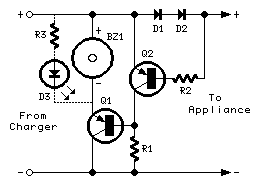
Broken Charger-connection Alert
The above circuit can be useful to detect if the load of any battery charger or plug-in adaptor supply is not properly connected. The load can be a set of batteries to be charged or any other type of battery...

Positive Voltage Reference Circuit
The circuit is designed for high precision operation over an extended temperature range, provided that V+ remains relatively constant, as the current IZ is dependent on V+. Resistors R1, R2, R3, and R4 are selected to ensure the appropriate IZ...

9400 Selling Leads 9400 Datasheet PDF
The absolute-value integrator circuit generates the effect of producing negative frequencies when the input signal is negative. It accomplishes this by allowing the counter to count up for positive voltage and count down for negative voltage. The specific types of...