


Nickel-cadmium battery charger LM324 constituted
#nickel-cadmium
#LM324
#battery management
#discharge circuit
#rechargeable battery
#voltage monitoring
#charging cycle
#memory effect
#power electronics
#energy storage

Description: The first circuit is designed for discharging nickel-cadmium batteries before recharging to eliminate the "memory effect." After discharging, the power is automatically converted to the state of charge. The charging process utilizes pulse-width modulation for constant current, along with a pulsating pulse discharge. It fully monitors the voltage across the battery and implements dual control, allowing for charging in parallel with an anti-charging function.
The described circuit serves a critical function in maintaining the health and efficiency of nickel-cadmium (NiCd) batteries by addressing the common "memory effect" that can occur with repeated partial discharge and recharge cycles. The circuit begins with a discharge phase, where the battery voltage is carefully monitored to ensure complete discharge. This is essential for resetting the battery's internal memory, allowing it to deliver maximum capacity upon recharging.
Once the discharge is complete, the circuit transitions to the charging phase. It employs pulse-width modulation (PWM) techniques to maintain a constant current during charging, which is vital for preventing overheating and prolonging battery life. The PWM method allows for precise control over the charging current, adapting to the battery's needs in real-time.
Additionally, the circuit incorporates a pulsating pulse discharge feature. This function helps to rejuvenate the battery by applying short bursts of discharge, which can help to break down any crystalline formations that may have developed on the battery cells, thereby restoring capacity.
The dual control mechanism ensures that the circuit can operate efficiently in both charging and discharging modes. This system allows for simultaneous charging of multiple batteries while preventing reverse current flow, which could damage the batteries or the circuit itself. The anti-charging feature acts as a safeguard, ensuring that batteries are not subjected to harmful conditions during the charging process.
Overall, this circuit design is an effective solution for managing the lifecycle of nickel-cadmium batteries, promoting optimal performance and longevity through careful monitoring and control of the discharge and charging processes.The first circuit of nickel-cadmium battery discharge before recharging to eliminate the "memory effect, after you put the power automatically converted to the state of charge. Charging a width modulation constant current, constant current charge plus pulsating pulse discharge, fully detect the voltage across the battery, and the implementation of dual control, charging in parallel with anti-anti-charging function.
The described circuit serves a critical function in maintaining the health and efficiency of nickel-cadmium (NiCd) batteries by addressing the common "memory effect" that can occur with repeated partial discharge and recharge cycles. The circuit begins with a discharge phase, where the battery voltage is carefully monitored to ensure complete discharge. This is essential for resetting the battery's internal memory, allowing it to deliver maximum capacity upon recharging.
Once the discharge is complete, the circuit transitions to the charging phase. It employs pulse-width modulation (PWM) techniques to maintain a constant current during charging, which is vital for preventing overheating and prolonging battery life. The PWM method allows for precise control over the charging current, adapting to the battery's needs in real-time.
Additionally, the circuit incorporates a pulsating pulse discharge feature. This function helps to rejuvenate the battery by applying short bursts of discharge, which can help to break down any crystalline formations that may have developed on the battery cells, thereby restoring capacity.
The dual control mechanism ensures that the circuit can operate efficiently in both charging and discharging modes. This system allows for simultaneous charging of multiple batteries while preventing reverse current flow, which could damage the batteries or the circuit itself. The anti-charging feature acts as a safeguard, ensuring that batteries are not subjected to harmful conditions during the charging process.
Overall, this circuit design is an effective solution for managing the lifecycle of nickel-cadmium batteries, promoting optimal performance and longevity through careful monitoring and control of the discharge and charging processes.The first circuit of nickel-cadmium battery discharge before recharging to eliminate the "memory effect, after you put the power automatically converted to the state of charge. Charging a width modulation constant current, constant current charge plus pulsating pulse discharge, fully detect the voltage across the battery, and the implementation of dual control, charging in parallel with anti-anti-charging function.

lm324 wave generator vco schematic
A voltage-controlled oscillator (VCO) using the LM324 operational amplifier is being developed, inspired by the Korg Monotron schematic. The goal is to create a simple circuit that produces audible waveforms, specifically square and triangle waves, when connected to a speaker....
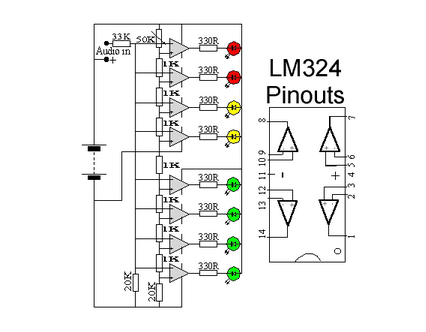
Audio VU Meter
This circuit utilizes two quad op-amps to create an eight LED audio level meter. The op-amp employed in this circuit is the LM324, which is a widely available integrated circuit. The 1K resistors in the circuit are crucial for activating...

FUZZ_CIRCUIT
Two diodes in the feedback path of an LM324 operational amplifier create a musical instrument effect known as fuzz by limiting the output voltage swing to ±0.7 V. The resultant square wave primarily contains odd harmonics, resembling the sounds of...

Tremolo
A phase shift oscillator utilizing the LM324 operates at an adjustable frequency range of 5-10 Hz, which is determined by a speed potentiometer. A segment of the oscillator output is extracted from the depth potentiometer and is employed to modulate...
FUZZ_CIRCUIT
Two diodes in the feedback path of an LM324 operational amplifier create a musical instrument effect known as fuzz by limiting the output voltage swing to ±0.7 V. The resultant square wave primarily contains odd harmonics, resembling the sounds of...

Simple circuit shuts off system when supply voltage is low
When the supply voltage drops below a minimum threshold, it is often advisable to disconnect the supply from the system to prevent poor performance or erratic operation. The circuit presented achieves this with minimal cost, board space, and complexity. Additionally,...

Linear LTC4151 Voltage
This power monitoring device accurately measures voltage and current on a positive supply rail ranging from 7V to 80V through a straightforward I2C interface, as specified in the datasheet. It is particularly suitable for automotive applications that require power monitoring...
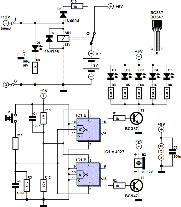
Mains Voltage Monitor
When the push button is pressed, a clock pulse appears on the CLK input of flip-flop IC1b. The output then toggles, causing the LEDs to turn off. Simultaneously, IC1a is reset, silencing the buzzer. Pressing the button again will turn...
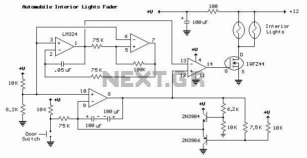
Automobile Interior Lights Fader
The automobile interior lights fader circuit diagram is designed to gradually brighten and dim the interior lights of older vehicles. This circuit utilizes the LM324 low-power operational amplifier as its core component.
The automobile interior lights fader circuit is an essential...