


resistors About a homemade SLA battery charger
#SLA battery
#resistors
#capacitors
#transistors
#educational
#homemade
#simple circuit
#DIY
#no IC
#basic components

Description: The circuit serves an educational purpose, necessitating simplicity. The construction will utilize only components that are already available, including a variety of resistors, capacitors, transistors, and no integrated circuits (ICs).
The circuit is designed to demonstrate fundamental electronic principles through a straightforward assembly of passive and active components. The choice of components, such as resistors and capacitors, allows for the exploration of basic concepts like voltage division, filtering, and time constants in RC circuits. Transistors will be employed to illustrate their role in signal amplification and switching functions.
For instance, a basic RC low-pass filter can be constructed using a resistor and capacitor in series, with the output taken across the capacitor. This configuration allows for the examination of how the circuit responds to different frequencies, providing insights into the behavior of reactive components. The cutoff frequency can be calculated using the formula f_c = 1 / (2πRC), where R is the resistance and C is the capacitance.
In addition, a simple transistor amplifier can be created using a common-emitter configuration. This setup will involve connecting a transistor with appropriate biasing resistors to ensure it operates in the active region. The input signal can be fed through a coupling capacitor to block any DC offset, while the output can be taken across the load resistor connected to the collector. This arrangement will allow for the analysis of gain and input/output characteristics.
By limiting the construction to available components, the circuit not only serves its educational purpose but also encourages resourcefulness and creativity in circuit design. Overall, this project aims to provide a practical understanding of basic electronic components and their interactions in simple circuits.The circuit has educational purpose, so being simple is a must. I`m also trying to build it only with components that I already have (a bunch of resistors, capacitors, transistors and none IC).
The circuit is designed to demonstrate fundamental electronic principles through a straightforward assembly of passive and active components. The choice of components, such as resistors and capacitors, allows for the exploration of basic concepts like voltage division, filtering, and time constants in RC circuits. Transistors will be employed to illustrate their role in signal amplification and switching functions.
For instance, a basic RC low-pass filter can be constructed using a resistor and capacitor in series, with the output taken across the capacitor. This configuration allows for the examination of how the circuit responds to different frequencies, providing insights into the behavior of reactive components. The cutoff frequency can be calculated using the formula f_c = 1 / (2πRC), where R is the resistance and C is the capacitance.
In addition, a simple transistor amplifier can be created using a common-emitter configuration. This setup will involve connecting a transistor with appropriate biasing resistors to ensure it operates in the active region. The input signal can be fed through a coupling capacitor to block any DC offset, while the output can be taken across the load resistor connected to the collector. This arrangement will allow for the analysis of gain and input/output characteristics.
By limiting the construction to available components, the circuit not only serves its educational purpose but also encourages resourcefulness and creativity in circuit design. Overall, this project aims to provide a practical understanding of basic electronic components and their interactions in simple circuits.The circuit has educational purpose, so being simple is a must. I`m also trying to build it only with components that I already have (a bunch of resistors, capacitors, transistors and none IC).

discussing output stage of square wave
The circuit includes 10K resistors at the bases of the transistors and 1K resistors at the collectors. It is essential to retain these components when relocating the transistors, as omitting the 10K resistors could result in transistor failure, and without...

5 Minute Signal
For the past year and a half, a group based in Ann Arbor, Michigan, named GO-Tech has been formed, uniting individuals interested in creating projects using technology, such as hardware, software, metal, and wood. This initiative is referred to as...

Homemade metal detector circuit
This homemade metal detector circuit will assist in locating objects made of materials with relatively high magnetic permeability. It is not suitable for detecting certain metals.
This metal detector circuit operates on the principle of electromagnetic induction, utilizing a coil of...

basic oscillator circuit using two
This schematic diagram represents a basic oscillator circuit utilizing two transistors. When the transistors and several passive components are connected as illustrated, the circuit begins to oscillate. The oscillation frequency can be modified by altering the values of either the...
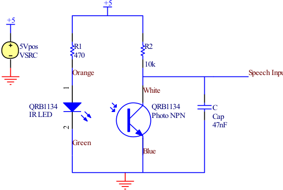
Circuit Schematics
All integrated circuits (ICs) are equipped with a 0.1 µF monolithic ceramic capacitor connected across their terminals. Additionally, each board features two capacitors: a 10 µF tantalum capacitor and a 100 µF electrolytic capacitor. The START BUTTON serves as a...

Homemade Metal Detector Kit
A simple home project can quickly become problematic if it encounters electric cables, gas, or water pipes, or the central heating system. Using a metal detector allows one to check for metal objects within walls, ceilings, or floors beforehand. An...

Homemade metal detector
This homemade metal detector circuit is designed to locate objects made of materials with relatively high magnetic permeability. While it may not be sensitive enough for detecting buried coins, it can effectively identify larger metallic treasures. The circuit operates using...

intercom circuit with transistors
The key to avoiding instability (motor-boating) in a high-gain circuit is to power the speaker using a separate power supply. This circuit design allows for the connection of one or two additional stations. It is recommended to construct the circuit...

muRata Manufacturing Measurement-Based SMT Capacitors
The schematic design of the equivalent circuit model for Murata Manufacturing's measurement-based GRH series SMT capacitors is derived from device measurements and modeling conducted by Murata. This model is applicable to capacitors mounted on an FR4 substrate, with constant substrate...