


Simple Lead Acid Battery Charger
#lead acid battery
#constant current
#current limiter
#voltage regulator
#transistor
#resistor
#fast-charging
#6-volt
#12-volt

Description: The above pictured schematic diagram is just a standard constant current model with a added current limiter, consisting of Q1, R1, and R4. The moment too much current is flowing biases Q1 and drops the output voltage. The output voltage is: 1.2 x (P1+R2+R3)/R3 volt. Current limiting kicks in when the current is about 0.6/R1 amp. For a 6-volt battery which requires fast-charging, the charge voltage is 3 x 2.45 = 7.35 V. (3 cells at 2.45v per cell). So the total value for R2 + P1 is then about 585 ohm. For a 12 V battery the value for R2 + P1 is then about 1290 ohm. More: For this power supply to work efficiently, the input voltage has to be a minimum of 3V higher than the output voltage. P1 is a standard trimmer potentiometer of sufficient watt for your application. The LM317 must be cooled on a sufficient (large) coolrib. Q1 (BC140) can be replaced with a NTE128 or the older ECG128 (same company). Except as a charger, this circuit can also be used as a regular power supply.
The described circuit is a constant current source with an integrated current limiting feature, primarily designed for charging applications but versatile enough to function as a standard power supply. The core components include a transistor (Q1), resistors (R1, R2, R3, R4), and a potentiometer (P1).
In operation, the circuit regulates current flow to prevent excessive output, which is crucial for protecting batteries during charging. When the current exceeds a predetermined threshold, Q1 becomes biased, leading to a reduction in output voltage. The output voltage formula, given as \( V_{out} = 1.2 \times \frac{(P1 + R2 + R3)}{R3} \), indicates that the output is influenced by the values of the resistors and the potentiometer, allowing for fine-tuning of the voltage output.
For battery charging, specific resistance values are calculated based on the battery voltage requirements. For instance, a 6V battery necessitates a charge voltage of 7.35V, which is derived from three cells at 2.45V each. The combined resistance of R2 and P1 is approximately 585 ohms for this configuration. Conversely, for a 12V battery, the required resistance value increases to about 1290 ohms.
The circuit's efficiency is contingent upon maintaining an input voltage that is at least 3V higher than the output voltage. This ensures that the LM317 voltage regulator operates within its optimal range. The LM317 requires adequate thermal management, necessitating the use of a sufficiently large heatsink to dissipate heat generated during operation.
The transistor Q1, specified as a BC140, can be substituted with alternatives such as the NTE128 or ECG128, which are compatible and maintain similar operational characteristics. The inclusion of a trimmer potentiometer (P1) allows for adjustable output, providing flexibility based on the specific application needs.
Overall, this circuit can be effectively utilized not only as a battery charger but also as a general-purpose power supply, making it a valuable design for various electronic projects.The above pictured schematic diagram is just a standard constant current model with a added current limiter, consisting of Q1, R1, and R4. The moment too much current is flowing biases Q1 and drops the output voltage. The output voltage is: 1.2 x (P1+R2+R3)/R3 volt. Current limiting kicks in when the current is about 0.6/R1 amp. For a 6-volt battery which requires fast-charging, the charge voltage is 3 x 2.45 = 7.35 V. (3 cells at 2.45v per cell). So the total value for R2 + P1 is then about 585 ohm. For a 12 V battery the value for R2 + P1 is then about 1290 ohm. For this power supply to work efficiently, the input voltage has to be a minimum of 3V higher than the output voltage. P1 is a standard trimmer potentiometer of sufficient watt for your application. The LM317 must be cooled on a sufficient (large) coolrib. Q1 (BC140) can be replaced with a NTE128 or the older ECG128 (same company). Except as a charger, this circuit can also be used as a regular power supply.
The described circuit is a constant current source with an integrated current limiting feature, primarily designed for charging applications but versatile enough to function as a standard power supply. The core components include a transistor (Q1), resistors (R1, R2, R3, R4), and a potentiometer (P1).
In operation, the circuit regulates current flow to prevent excessive output, which is crucial for protecting batteries during charging. When the current exceeds a predetermined threshold, Q1 becomes biased, leading to a reduction in output voltage. The output voltage formula, given as \( V_{out} = 1.2 \times \frac{(P1 + R2 + R3)}{R3} \), indicates that the output is influenced by the values of the resistors and the potentiometer, allowing for fine-tuning of the voltage output.
For battery charging, specific resistance values are calculated based on the battery voltage requirements. For instance, a 6V battery necessitates a charge voltage of 7.35V, which is derived from three cells at 2.45V each. The combined resistance of R2 and P1 is approximately 585 ohms for this configuration. Conversely, for a 12V battery, the required resistance value increases to about 1290 ohms.
The circuit's efficiency is contingent upon maintaining an input voltage that is at least 3V higher than the output voltage. This ensures that the LM317 voltage regulator operates within its optimal range. The LM317 requires adequate thermal management, necessitating the use of a sufficiently large heatsink to dissipate heat generated during operation.
The transistor Q1, specified as a BC140, can be substituted with alternatives such as the NTE128 or ECG128, which are compatible and maintain similar operational characteristics. The inclusion of a trimmer potentiometer (P1) allows for adjustable output, providing flexibility based on the specific application needs.
Overall, this circuit can be effectively utilized not only as a battery charger but also as a general-purpose power supply, making it a valuable design for various electronic projects.The above pictured schematic diagram is just a standard constant current model with a added current limiter, consisting of Q1, R1, and R4. The moment too much current is flowing biases Q1 and drops the output voltage. The output voltage is: 1.2 x (P1+R2+R3)/R3 volt. Current limiting kicks in when the current is about 0.6/R1 amp. For a 6-volt battery which requires fast-charging, the charge voltage is 3 x 2.45 = 7.35 V. (3 cells at 2.45v per cell). So the total value for R2 + P1 is then about 585 ohm. For a 12 V battery the value for R2 + P1 is then about 1290 ohm. For this power supply to work efficiently, the input voltage has to be a minimum of 3V higher than the output voltage. P1 is a standard trimmer potentiometer of sufficient watt for your application. The LM317 must be cooled on a sufficient (large) coolrib. Q1 (BC140) can be replaced with a NTE128 or the older ECG128 (same company). Except as a charger, this circuit can also be used as a regular power supply.

Nicad Battery Charger
This simple charger utilizes a single transistor as a constant current source. The voltage across a pair of 1N4148 diodes biases the base of the BD140 medium power transistor. The base-emitter voltage of the transistor and the forward voltage drop...
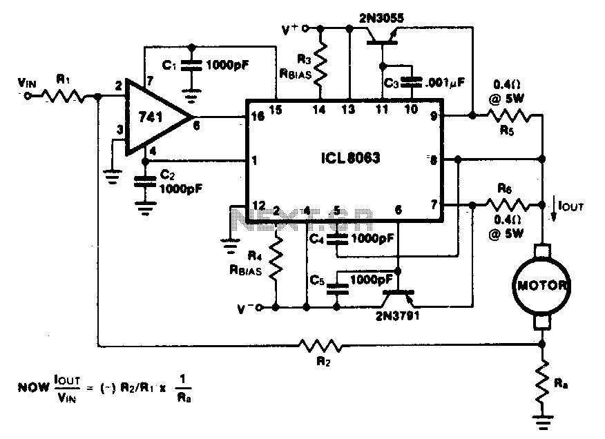
Constant current motor drive circuit
This minimum device circuit can be used to drive DC motors where there is some likelihood of stalling or lock-up. If the motor locks, the current drive remains constant, and the system does not destroy itself.
This circuit is designed to...

A common collector amplifier
A common collector amplifier circuit structure and its key components are outlined. The composition of the common collector amplifier circuit is fundamentally similar to that of a common emitter amplifier circuit, with two notable exceptions: one is the collector resistor...

12 Volt 30 Amp PSU
Using a single 7812 IC voltage regulator and multiple outboard pass transistors, this power supply can deliver output load currents of up to 30 amps. The input transformer is likely to be the most expensive part of the entire project....
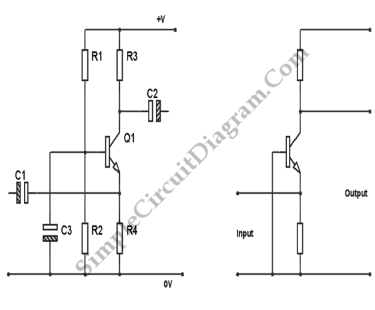
Transistor Common Base Amplifier
In terms of AC signals, the base is connected to the ground through capacitor C3. Consequently, both the input and output are linked to the base, forming a common base amplifier configuration.
The common base amplifier is a type of transistor...

Voltage-controlled amplifier or tremolo circuit
The transistors create a differential pair with an active current-source tail. This configuration, referred to as a variable-transconductance multiplier, produces an output that is proportional to the product of the two input signals. The multiplication effect arises from the dependence...

Anti-saturation function delete circuit schematics
Anti-saturation devices have been removed from the UAA4002 routine applications. The base current of the switching transistor, which is driven by another transistor, is automatically adjusted. This adjustment allows the power transistors to operate in critical saturation. However, when the...

Transistor Circuits
It had been a little over a decade since the invention of the transistor when this article appeared in the August 1959 edition of Popular Electronics. Transistors were still a mystery to many, including engineers, technicians, and hobbyists. Author James...
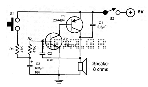
Noise making circuits
The core of the circuit is a two-transistor flasher with frequency modulation applied to the base of the first transistor. When the pushbutton is pressed, the oscillation frequency increases to a peak, and upon release, the frequency decreases due to...