


Simple Ni-Cd Battery Charger
#Ni-Cd
#LM317
#voltage regulator
#charging circuit
#current control
#resistor
#simple circuit
#mA to A range
#battery management
#DIY charger
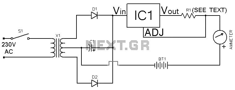
Description: This Ni-Cd battery charger is a circuit utilizing the LM317 regulator IC. The design is straightforward and requires minimal components. By adjusting the value of resistor R1 between 1 ohm and 120 ohms, the charging current can be modified from milliamps to 1.25 A.
The Ni-Cd battery charger circuit employs the LM317 voltage regulator, which is a versatile and widely used component in power supply applications. The LM317 is capable of providing a stable output voltage and can be configured to deliver a specific current for charging purposes. In this design, the charging current is controlled by a variable resistor (R1), allowing for flexibility in charging different capacities of Ni-Cd batteries.
The circuit typically consists of the LM317 IC, a few passive components including R1, and additional resistors and capacitors to stabilize the output and improve performance. The input voltage must be higher than the desired output voltage, which is typically set to around 1.2 V for Ni-Cd batteries. The current flowing through the battery can be adjusted by changing the resistance value of R1, thus allowing the circuit to accommodate various battery sizes and charging requirements.
For optimal performance, it is recommended to include a heat sink for the LM317, as it can generate heat during operation, especially when charging at higher currents. A diode may also be placed in parallel with the battery to prevent reverse current flow when the charger is disconnected.
In summary, this Ni-Cd battery charger circuit is an efficient and adaptable solution for charging Ni-Cd batteries, leveraging the capabilities of the LM317 voltage regulator to provide a controlled charging current through simple component adjustments.This Ni-Cd battery charger is a circuit based on the regulator IC lm317.This circuit is very simple and uses minimum components. By varying value of resistor R1 from 1 ohm to 120 ohms, charging current can be varied from mA to 1.25 A.
Th..
The Ni-Cd battery charger circuit employs the LM317 voltage regulator, which is a versatile and widely used component in power supply applications. The LM317 is capable of providing a stable output voltage and can be configured to deliver a specific current for charging purposes. In this design, the charging current is controlled by a variable resistor (R1), allowing for flexibility in charging different capacities of Ni-Cd batteries.
The circuit typically consists of the LM317 IC, a few passive components including R1, and additional resistors and capacitors to stabilize the output and improve performance. The input voltage must be higher than the desired output voltage, which is typically set to around 1.2 V for Ni-Cd batteries. The current flowing through the battery can be adjusted by changing the resistance value of R1, thus allowing the circuit to accommodate various battery sizes and charging requirements.
For optimal performance, it is recommended to include a heat sink for the LM317, as it can generate heat during operation, especially when charging at higher currents. A diode may also be placed in parallel with the battery to prevent reverse current flow when the charger is disconnected.
In summary, this Ni-Cd battery charger circuit is an efficient and adaptable solution for charging Ni-Cd batteries, leveraging the capabilities of the LM317 voltage regulator to provide a controlled charging current through simple component adjustments.This Ni-Cd battery charger is a circuit based on the regulator IC lm317.This circuit is very simple and uses minimum components. By varying value of resistor R1 from 1 ohm to 120 ohms, charging current can be varied from mA to 1.25 A.
Th..

5V FET Voltage Regulator
This voltage regulator circuit provides a stable 5V output from unregulated inputs that are greater than 5V. The output voltage stability is satisfactory, with minimal variations.
The voltage regulator circuit utilizes a linear voltage regulator, such as the LM7805, which is...

BMW R Series Motorcycle Regulator Schematic
Correctly adjusted, the voltage on the pot wiper is slightly less than half D+ (appx. 0.47*D+) and Q1 will conduct if (D+)-(Vp) > 6.2 + 0.7 + 0.7, or 0.53*(D+) > 7.6V, (D+) > 14.3V. If D+ is lower than...
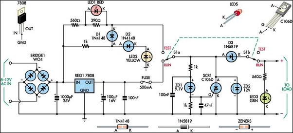
8V DC Power Supply With Over Voltage Protection
This 8V DC power supply is designed for use with high-end electronic equipment. It includes full over-voltage protection to safeguard against regulator failure, whether in the supply itself or in the connected device. The circuit employs a standard full-wave rectifier,...
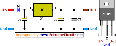
9 Volt 2 Ampere DC Power SupplyCircuit
A simple 9 Volt, 2 amp power supply utilizing a single integrated circuit (IC) regulator. This circuit is straightforward, as the regulator handles the majority of the work. The component used is the 7809 voltage regulator.
The circuit consists primarily of...

Overvoltage Protection for the LM317
It is a voltage regulator that allows a 6v portable supply to be derived from the 12v car battery. You can add a 6.2V zener diode and a LED to warn you when the input supply is overvoltage. If you...

Power supply +20V/15A and +12V/3A
The circuit is based on application of National Semiconductor. First is constituted by three voltage regulators LM338 [IC1-2-3] connected in parallel. The each one regulator has the possibility of giving 5 A in his output. Also exists the possibility to...

12-16V-converter
Many devices operate from a car's 12-V electrical system. Some require 12 V, while others need a lower voltage. An automobile battery's output can vary from 12 to 13.8 V under normal circumstances. The load requirements of the device may...

90Vrms voltage regulator
The circuit is an open-loop RMS voltage regulator designed to deliver 500 watts of power at 90 V RMS, maintaining good regulation within an input voltage range of 110-130 V RMS. When the input voltage is applied, capacitor C1 charges...

Fully Adjustable Power Supply
This circuit, based on a National Semiconductor application note, utilizes an LM317 3-terminal regulator (REG1) due to its integrated over-current and over-temperature protection features. The output current is amplified to slightly over 5A using the MJ2955 transistor (Q1). The output...