


Single cell charger
#single cell
#charger
#full-charge detection
#float condition
#240 mA
#12 mA
#automatic switching
#battery management

Description: This circuit detects a full-charge state and automatically switches to a float condition—from 240 mA to 12 mA. The circuit uses the 555 timer.
The described circuit is designed to monitor the charging state of a battery and to transition between a high current charging mode and a low current float mode to maintain battery health and longevity. The 555 timer integrated circuit serves as the core component for timing and control functions.
In the charging phase, the circuit allows a current of 240 mA to flow into the battery. This is achieved by configuring the 555 timer in monostable or astable mode, depending on the desired timing characteristics. The output of the timer can control a transistor or a relay that connects the power supply to the battery.
Once the battery reaches a pre-set voltage level, indicating a full charge, the 555 timer detects this state through a voltage divider network connected to the battery terminals. Upon detection of the full charge, the timer output switches state, reducing the current to a float level of 12 mA. This transition is critical as it prevents overcharging, which can lead to battery damage or reduced lifespan.
The float state is maintained by adjusting the duty cycle of the 555 timer, ensuring that the battery remains topped off without excessive current flow. The circuit may also include additional components such as diodes for reverse polarity protection and capacitors for smoothing voltage fluctuations.
Overall, this circuit effectively manages battery charging by utilizing the 555 timer's versatile timing capabilities, ensuring both efficient charging and safe maintenance of the battery's state of charge.This circuit detects a full-charge state and automatically switches to a float condition—from 240 mA to 12 mA. The circuit uses the 555 timer.
The described circuit is designed to monitor the charging state of a battery and to transition between a high current charging mode and a low current float mode to maintain battery health and longevity. The 555 timer integrated circuit serves as the core component for timing and control functions.
In the charging phase, the circuit allows a current of 240 mA to flow into the battery. This is achieved by configuring the 555 timer in monostable or astable mode, depending on the desired timing characteristics. The output of the timer can control a transistor or a relay that connects the power supply to the battery.
Once the battery reaches a pre-set voltage level, indicating a full charge, the 555 timer detects this state through a voltage divider network connected to the battery terminals. Upon detection of the full charge, the timer output switches state, reducing the current to a float level of 12 mA. This transition is critical as it prevents overcharging, which can lead to battery damage or reduced lifespan.
The float state is maintained by adjusting the duty cycle of the 555 timer, ensuring that the battery remains topped off without excessive current flow. The circuit may also include additional components such as diodes for reverse polarity protection and capacitors for smoothing voltage fluctuations.
Overall, this circuit effectively manages battery charging by utilizing the 555 timer's versatile timing capabilities, ensuring both efficient charging and safe maintenance of the battery's state of charge.This circuit detects a full-charge state and automatically switches to a float condition—from 240 mA to 12 mA. The circuit uses the 555 timer.

Charger circuit equipped with a regulator circuit output voltage Schematic Diagram
The charging circuit features adjustable voltage output settings, allowing for regulation of the charging voltage supplied to the battery. The use of a potentiometer facilitates precise voltage management, with adjustments possible down to the millivolt range. Refer to the charger...

Charger circuit V
The charger operates with a charging voltage of 2.4 V per cell, aligning with the recommendations of most manufacturers. The circuit delivers a charging voltage of 14.4 V (6 cells at 2.4 V per cell) in a pulsed manner at...
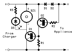
Broken Charger-connection Alert
The above circuit can be useful to detect if the load of any battery charger or plug-in adaptor supply is not properly connected. The load can be a set of batteries to be charged or any other type of battery...

charger
The circuit was constructed on a Vero board and tested with a large electrolytic capacitor in place of a battery. A 500-ohm preset resistor determines the output voltage, while a 47k preset resistor regulates the hysteresis and establishes the voltage...
Broken Charger-connection Alert
The above circuit can be useful to detect if the load of any battery charger or plug-in adaptor supply is not properly connected. The load can be a set of batteries to be charged or any other type of battery...

simple accu charger circuit
The Accu charger circuit is straightforward and simple to construct, requiring no more than ten components. In addition to its ease of assembly, this charger circuit is also cost-effective and highly efficient. The circuit requires a power supply from a...