


solar battery charger circuit schematic
#solar
#voltage regulation
#current limiting
#transistor
#zener diode
#battery protection
#adjustable output
#charging circuit
#energy harvesting

Description: By adjusting the Adjust pin, the output voltage and current can be regulated. A variable resistor (VR) is connected between the Adjust pin and ground to achieve an output voltage of 9 volts to the battery. Resistor R3 limits the charging current, while diode D2 prevents the discharge of current from the battery. Transistor T1 and Zener diode ZD function as a cutoff switch when the battery is fully charged. Normally, T1 remains off, allowing the battery to receive charging current. When the terminal voltage of the battery exceeds 6.8 volts, the Zener diode conducts and supplies base current to T1.
The described circuit operates as a battery charger with adjustable output voltage and current regulation. The Adjust pin serves as a control point for the charging voltage, and the variable resistor (VR) allows fine-tuning of this voltage to ensure optimal charging conditions for the battery, which is set at 9 volts in this configuration.
The inclusion of resistor R3 is critical as it restricts the charging current to a safe level, preventing potential damage to the battery from excessive current. The diode D2 plays an essential role in maintaining the integrity of the charging circuit by blocking reverse current flow, thus ensuring that the battery does not discharge back into the charger when it is not in operation.
Transistor T1 is utilized as a switch in conjunction with the Zener diode ZD. Under normal operating conditions, T1 remains in the off state, allowing the charging current to flow to the battery. However, when the battery's terminal voltage rises above the Zener voltage of 6.8 volts, ZD begins to conduct, providing sufficient base current to turn on T1. This action effectively disconnects the charging current from the battery, preventing overcharging and ensuring the longevity of the battery.
Overall, this circuit design emphasizes safety and efficiency in battery charging, leveraging components such as resistors, diodes, and transistors to create a reliable and adjustable charging solution. Proper selection of components and values is crucial to achieving the desired performance and protecting both the battery and the charging circuit.By adjusting its Adjust pin, output voltage and current can beregulated. VR is placed between the adjust pin and ground to provide an output voltage of 9 volts tothe battery. Resistor R3 Restrict the charging current and diode D2 prevents discharge ofcurrent from the battery.
Transistor T1 and Zener diode ZD act as a cut off switch whenthe battery is full. Normally T1 is off and battery gets charging current. When the terminal voltage of the battery rises above 6. 8 volts, Zener conducts andprovides base current to T1.
The described circuit operates as a battery charger with adjustable output voltage and current regulation. The Adjust pin serves as a control point for the charging voltage, and the variable resistor (VR) allows fine-tuning of this voltage to ensure optimal charging conditions for the battery, which is set at 9 volts in this configuration.
The inclusion of resistor R3 is critical as it restricts the charging current to a safe level, preventing potential damage to the battery from excessive current. The diode D2 plays an essential role in maintaining the integrity of the charging circuit by blocking reverse current flow, thus ensuring that the battery does not discharge back into the charger when it is not in operation.
Transistor T1 is utilized as a switch in conjunction with the Zener diode ZD. Under normal operating conditions, T1 remains in the off state, allowing the charging current to flow to the battery. However, when the battery's terminal voltage rises above the Zener voltage of 6.8 volts, ZD begins to conduct, providing sufficient base current to turn on T1. This action effectively disconnects the charging current from the battery, preventing overcharging and ensuring the longevity of the battery.
Overall, this circuit design emphasizes safety and efficiency in battery charging, leveraging components such as resistors, diodes, and transistors to create a reliable and adjustable charging solution. Proper selection of components and values is crucial to achieving the desired performance and protecting both the battery and the charging circuit.By adjusting its Adjust pin, output voltage and current can beregulated. VR is placed between the adjust pin and ground to provide an output voltage of 9 volts tothe battery. Resistor R3 Restrict the charging current and diode D2 prevents discharge ofcurrent from the battery.
Transistor T1 and Zener diode ZD act as a cut off switch whenthe battery is full. Normally T1 is off and battery gets charging current. When the terminal voltage of the battery rises above 6. 8 volts, Zener conducts andprovides base current to T1.
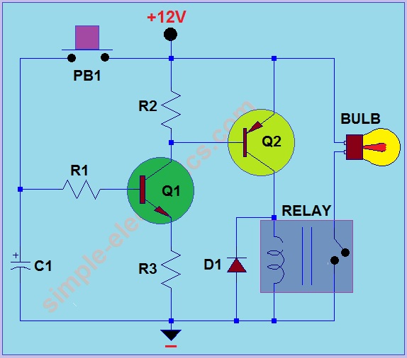
Car Headlight with Delay Circuit
This circuit operates by activating a headlight when the push-button PB1 is pressed. The headlight remains illuminated for a predetermined duration, which can range from several seconds to minutes, before automatically turning off. When PB1 is engaged, capacitor C1 begins...
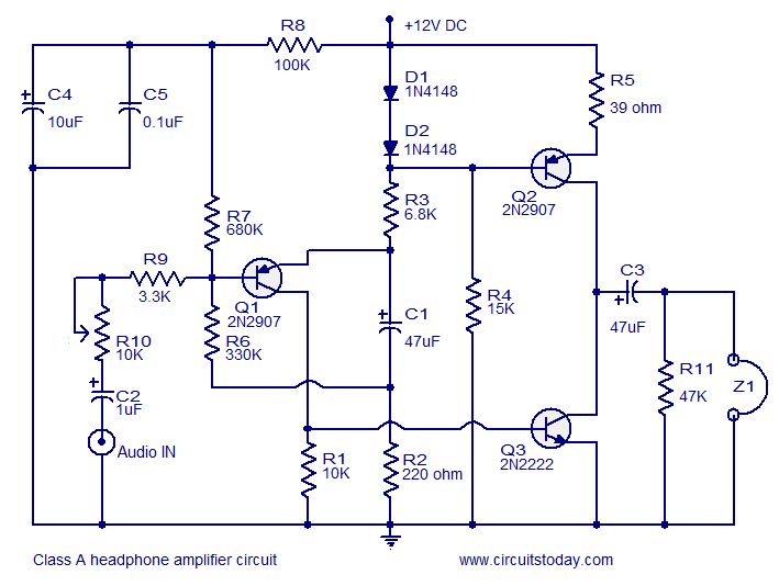
Transistor amplifier circuits
Transistor amplifier circuits that are simple and easy to construct. This includes a headphone amplifier, a four-transistor amplifier, and a low-power amplifier.
Transistor amplifier circuits are fundamental components in electronic design, offering various applications ranging from audio amplification to signal processing....

2 transistor fm voice transmitter
This circuit functions as a voice transmitter utilizing a pair of BC548 transistors. While these transistors are not specifically designed for RF applications, they still yield satisfactory performance. An ECM microphone insert from Maplin Electronics, order code FS43W, is employed....

AC arc welding machine transistor load power path from 2
The AC arc welding machine's transistor load path for the power from the second circuit is illustrated. The figure shows a current transformer with a core cross-section of 25 mm². The transformer has a primary winding with a certain number...

Transistor Circuits Design
Transistors are essential components of electronic circuits. The success of a circuit design depends on the selection of the appropriate transistor type and the calculations involved.
Transistors serve as fundamental building blocks in electronic circuits, playing critical roles in amplification, switching,...

A variable frequency oscillating circuit transistor
A variable frequency oscillator transistor circuit, primarily functioning as an oscillator, incorporates a crystal resonator and a varactor diode. The output is amplified, typically used for generating high-frequency signals. This 30 MHz transistor circuit features an inductor (LP) connected to...
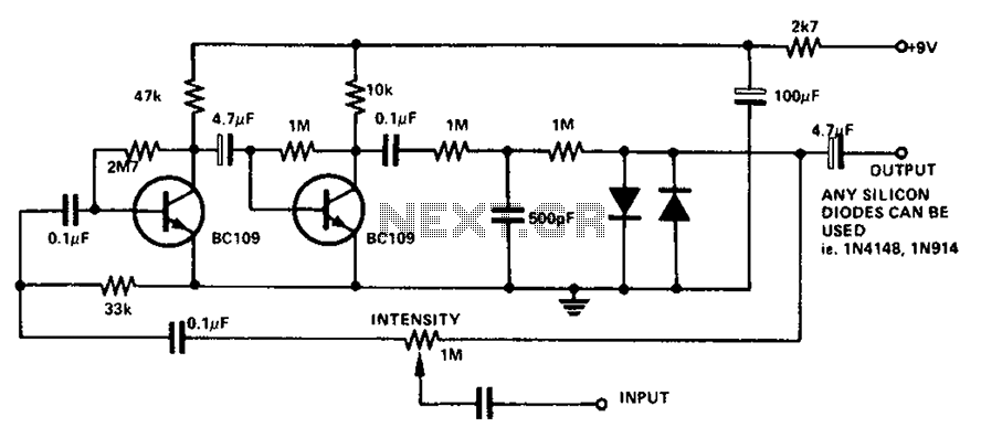
Boombox circuit diagram
The circuit utilizes a transistor to amplify the input signal. Two diodes are employed to clamp the distorted output, while a 500 pF capacitor filters out high-frequency noise. Under normal conditions, a 1M slide rheostat is used to adjust the...

1 Transistor Toggle Relay schematic
The circuit below requires a double pole, double throw relay in conjunction with a single transistor to allow toggling the relay with a momentary push button. One set of relay contacts is used to control the load, while the other...

capacitor Explaining a car voltage regulator circuit
The circuit regulates approximately 12V from the car battery down to 5V for use by an Atmel AVR microcontroller. The presence of two capacitors on each side of the linear regulator LM7805 raises questions regarding their purpose. It is suggested...