


Temperature Controlled NICD Charger
#temperature controlled
#NICD
#NIMH
#rechargeable
#constant current
#battery charger
#overcharge protection
#cell life
#electrolyte

Description: This circuit is for a temperature controlled constant current battery charger. It works with NICD, NIMH, and other rechargeable cells. The circuit works on the principle that most rechargeable batteries show an increase in temperature when the cells become fully charged. Overcharging is one of the main causes of short cell life; hot cells pop their internal seals and vent out electrolyte. As cells dry out, they lose capacity. The transformer, bridge rectifier, and 1000uF capacitor provide around 22 Volts of DC power to run the rest of the circuit. The 7812 regulator drops this to 12V to run the 311 comparator and 4011 nand gates. The start switch is pressed to start the charging process.
The described circuit functions as a temperature-controlled constant current battery charger, specifically designed for nickel-cadmium (NiCd), nickel-metal hydride (NiMH), and similar rechargeable battery types. The fundamental operation relies on the thermal response of the batteries; as they reach full charge, their internal temperature rises, which is monitored to prevent overcharging—a significant factor in prolonging battery life.
The initial power stage of the circuit includes a transformer that steps down the AC mains voltage to a lower AC voltage suitable for charging. Following this, a bridge rectifier converts the AC voltage to pulsating DC, which is then smoothed by a 1000µF capacitor, resulting in approximately 22V of DC power. This voltage is necessary to ensure that the subsequent components in the circuit receive adequate power.
To regulate this voltage, a 7812 voltage regulator is employed, which steps down the voltage to a stable 12V. This regulated output is crucial for the operation of the LM311 voltage comparator and the 4011 NAND gates that are integral to the control logic of the charger. The LM311 comparator serves to monitor the voltage across the battery, while the NAND gates are used to implement the control logic that manages the charging process.
The circuit is initiated by pressing a start switch, which activates the charging sequence. This switch connects the power supply to the charging circuitry, allowing the charger to begin monitoring the battery's voltage and temperature. The control logic ensures that the charging current remains constant until the battery temperature indicates it is fully charged, at which point the charging process is halted to prevent damage from overcharging.
In summary, this temperature-controlled constant current battery charger is a vital circuit designed to safely charge rechargeable batteries while monitoring their thermal characteristics to prevent overcharging and extend battery life. The combination of a transformer, rectifier, smoothing capacitor, voltage regulator, comparator, and logic gates creates a robust and efficient charging solution.This circuit is for a temperature controlled constant current battery charger. It works with NICD, NIMH, and other rechargeable cells. The circuit works on the principle that most rechargeable batteries show an increase in temperature when the cells becomes fully charged. Overcharging is one of the main causes of short cell life, hot cells pop their internal seals and vent out electrolyte.
As cells dry out, they lose capacity. The transformer, bridge rectifier, and 1000uF capacitor provide around 22 Volts of DC power to run the rest of the circuit. The 7812 regulator drops this to 12V to run the 311 comparator and 4011 nand gates. The start switch is pressed to start the cha
The described circuit functions as a temperature-controlled constant current battery charger, specifically designed for nickel-cadmium (NiCd), nickel-metal hydride (NiMH), and similar rechargeable battery types. The fundamental operation relies on the thermal response of the batteries; as they reach full charge, their internal temperature rises, which is monitored to prevent overcharging—a significant factor in prolonging battery life.
The initial power stage of the circuit includes a transformer that steps down the AC mains voltage to a lower AC voltage suitable for charging. Following this, a bridge rectifier converts the AC voltage to pulsating DC, which is then smoothed by a 1000µF capacitor, resulting in approximately 22V of DC power. This voltage is necessary to ensure that the subsequent components in the circuit receive adequate power.
To regulate this voltage, a 7812 voltage regulator is employed, which steps down the voltage to a stable 12V. This regulated output is crucial for the operation of the LM311 voltage comparator and the 4011 NAND gates that are integral to the control logic of the charger. The LM311 comparator serves to monitor the voltage across the battery, while the NAND gates are used to implement the control logic that manages the charging process.
The circuit is initiated by pressing a start switch, which activates the charging sequence. This switch connects the power supply to the charging circuitry, allowing the charger to begin monitoring the battery's voltage and temperature. The control logic ensures that the charging current remains constant until the battery temperature indicates it is fully charged, at which point the charging process is halted to prevent damage from overcharging.
In summary, this temperature-controlled constant current battery charger is a vital circuit designed to safely charge rechargeable batteries while monitoring their thermal characteristics to prevent overcharging and extend battery life. The combination of a transformer, rectifier, smoothing capacitor, voltage regulator, comparator, and logic gates creates a robust and efficient charging solution.This circuit is for a temperature controlled constant current battery charger. It works with NICD, NIMH, and other rechargeable cells. The circuit works on the principle that most rechargeable batteries show an increase in temperature when the cells becomes fully charged. Overcharging is one of the main causes of short cell life, hot cells pop their internal seals and vent out electrolyte.
As cells dry out, they lose capacity. The transformer, bridge rectifier, and 1000uF capacitor provide around 22 Volts of DC power to run the rest of the circuit. The 7812 regulator drops this to 12V to run the 311 comparator and 4011 nand gates. The start switch is pressed to start the cha

NiMH / Nicad Charger
I specifically designed this circuit to charge 2 batteries for my digital cameras, but it can be modified to charge 3, 4, 5, or more cells. However, it will not work with only one cell as that voltage is too...

NiCd battery ChargerCircuit With TLC555 IC
The following circuit illustrates a portable NiCd battery charger circuit diagram. The portable battery charger is designed to facilitate the charging of nickel-cadmium batteries.
The portable NiCd battery charger circuit typically consists of several key components, including a transformer, rectifier, voltage...

Optimizing the Load-Switch Function of the DS2715 Battery-Charger IC
The DS2715 is a comprehensive NiMH (Nickel Metal Hydride) smart charger solution featuring load detection, making it ideal for cost-effective applications.
The DS2715 smart charger integrates several key functionalities designed to enhance the charging process for NiMH batteries. It employs advanced...

Power Supply
This system serves as the power supply for all the circuitry within the robot, as illustrated in the block diagram. Housed within an aluminum enclosure are the NiMH cells along with the previously described circuits. Two lines of preregulators are...

Battery Charger
This high-performance charger efficiently charges gelled lead-acid batteries and automatically shuts off upon reaching a full charge. Initially, the charging current is maintained at 2 A; however, as the battery voltage increases, the current gradually decreases. Once the current drops...

14 Volt Battery Charger Circuit Schematic Diagram
This circuit outputs a voltage of 14 volts with a maximum current of 4A. It can be used for NiCad batteries and accumulators, both wet and dry types. However, the accumulator must be rated for 12 volts and have a...
Battery Charger
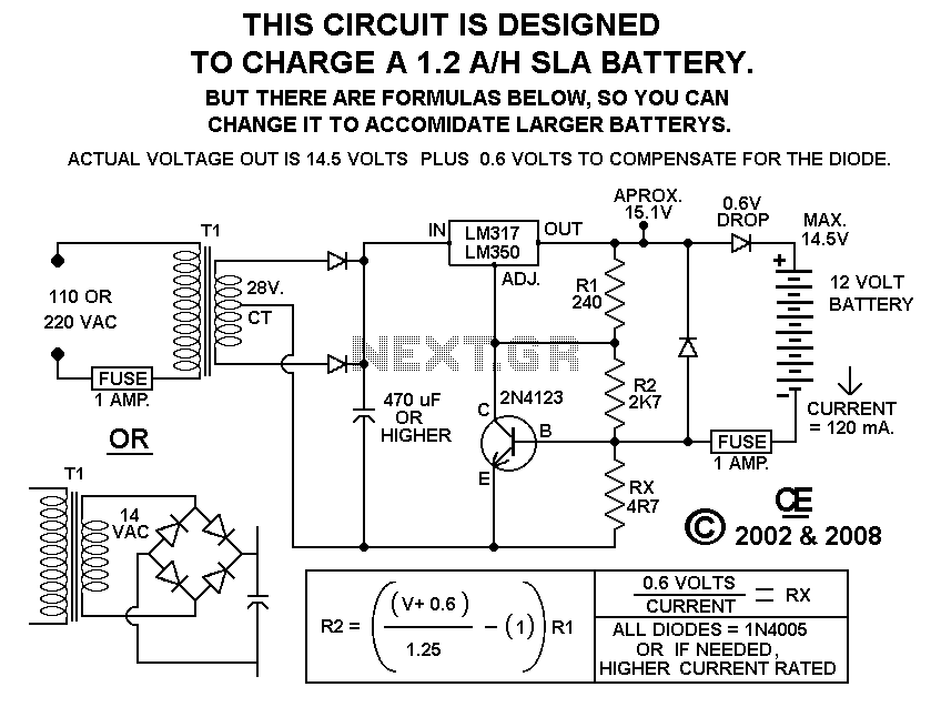
Using this circuit will give good charging results to the gel cell battery used in the metal detector or any other similar and smaller type battery. This charger is both current and voltage regulated. The output is not short circuit...

BQ24400 Switch-mode NiCd/NiMH Battery Charger With Peak Voltage Detection Termination
The BU8732AKV is a PCM codec integrated circuit (IC) designed for digital cellular phones. It features a variety of analog input and output functions, including a 14-bit precision linear A-LAW codec, a microphone amplifier with dual systems, amplifiers for both...

battery charger circuits
Several schematic drawings of battery charger circuits are provided. These circuits cover 5W to 200W for NiCd, NiMH, Lead-Acid, Li-Ion/Polymer, and LiFePO4 battery packs. The charger circuit files aim to assist users in selecting the appropriate chargers and to enhance...