


USB Powered Mobile Phone Battery Charger
#USB powered
#mobile phone
#regulated voltage
#slow charging
#NiMh
#Lithium cells
#4.7 volts
#5 volts DC
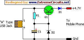
Description: This simple circuit provides a regulated output of 4.7 volts for charging a mobile phone. A USB outlet supplies 5 volts DC at 100mA, which is adequate for slow charging of mobile phones. Most mobile phone batteries are rated at 3.6 volts with capacities ranging from 1000 to 1300 mAh. These battery packs typically consist of three NiMH or lithium cells, each rated at 1.2 volts. Generally, a battery pack requires 4.5 volts at a current of 300-500 mA for fast charging. However, charging at a lower current is more efficient for battery longevity. The circuit described here delivers a regulated output of 4.7 volts and sufficient current for slow charging of mobile phones. Transistor Q1 is employed to provide the regulated output. Any medium power NPN transistor, such as CL100, BD139, or TIP122, can be utilized. The Zener diode D2 regulates the output voltage, while diode D1 protects against reverse polarity. The front end of the circuit should be connected to a Type A USB plug, with the red wire attached to pin 1 and the black wire to pin 4 for easy polarity identification. The output should be connected to an appropriate charger pin to interface with the mobile phone. After assembling the circuit, the USB plug can be inserted into the socket to measure the output. If the output is satisfactory and the polarity is correct, the circuit can be connected to the mobile phone.
This circuit is designed to deliver a stable 4.7 volts necessary for the optimal charging of mobile phone batteries, which typically require a lower voltage than what is provided by standard USB outputs. The use of a medium power NPN transistor allows for adequate regulation of the voltage, ensuring that the output remains consistent despite variations in input voltage or load conditions.
The Zener diode D2 plays a crucial role in maintaining the desired output voltage by shunting excess voltage away from the load, thereby preventing overcharging and potential damage to the battery. The inclusion of diode D1 is essential for protecting the circuit from reverse polarity connections, which could otherwise lead to circuit failure or damage.
The choice of a Type A USB plug for the front end of the circuit is practical, as it allows for compatibility with a wide range of power sources, including wall chargers and computer USB ports. The specified wiring connections (red to pin 1 and black to pin 4) facilitate straightforward identification of positive and negative terminals, minimizing the risk of incorrect connections during assembly.
For assembly, it is recommended to use a breadboard or a similar prototyping platform to test the circuit before finalizing the design. Once the circuit is assembled, measuring the output voltage with a multimeter will confirm that it is within the desired range. If the voltage is stable and the polarity is correct, the circuit can be safely connected to the mobile phone for charging. This design effectively balances the need for a regulated output with the efficiency of low-current charging, promoting the longevity of lithium-ion or NiMH batteries commonly used in mobile devices.This simple circuit can give regulated 4. 7 volts for charging a mobile phone. USB outlet can give 5 volts DC at 100mA current which is sufficient for the slow charging of mobile phones. Most of the Mobile Phone batteries are rated 3. 6 volts at 1000 to 1300 mAh. These battery packs have 3 NiMh or Lithium cells having 1. 2 volt rating. Usually the ba ttery pack requires 4. 5 volts at 300-500 mA current for fast charging. But low current charging is better to increase the efficiency of the battery. The circuit described here provides 4. 7 regulated voltage and sufficient current for the slow charging of the mobile phone. Transistor Q1 is used to give the regulated output. Any medium power NPN transistor like CL100, BD139, TIP122 can be used. Zener diode D2 controls the output voltage and D1 protects the polarity of the output supply. Front end of the circuit should be connected to a A type USB plug. Connect a red wire to pin1 and black wire to pin 4 of the plug for easy polarity identification. Connect the output to a suitable charger pin to connect it with the mobile phone. After assembling the circuit, insert the USB plug into the socket and measure the output from the circuit. If the output is OK and polarity is correct, connect it with the mobile phone.
This circuit is designed to deliver a stable 4.7 volts necessary for the optimal charging of mobile phone batteries, which typically require a lower voltage than what is provided by standard USB outputs. The use of a medium power NPN transistor allows for adequate regulation of the voltage, ensuring that the output remains consistent despite variations in input voltage or load conditions.
The Zener diode D2 plays a crucial role in maintaining the desired output voltage by shunting excess voltage away from the load, thereby preventing overcharging and potential damage to the battery. The inclusion of diode D1 is essential for protecting the circuit from reverse polarity connections, which could otherwise lead to circuit failure or damage.
The choice of a Type A USB plug for the front end of the circuit is practical, as it allows for compatibility with a wide range of power sources, including wall chargers and computer USB ports. The specified wiring connections (red to pin 1 and black to pin 4) facilitate straightforward identification of positive and negative terminals, minimizing the risk of incorrect connections during assembly.
For assembly, it is recommended to use a breadboard or a similar prototyping platform to test the circuit before finalizing the design. Once the circuit is assembled, measuring the output voltage with a multimeter will confirm that it is within the desired range. If the voltage is stable and the polarity is correct, the circuit can be safely connected to the mobile phone for charging. This design effectively balances the need for a regulated output with the efficiency of low-current charging, promoting the longevity of lithium-ion or NiMH batteries commonly used in mobile devices.This simple circuit can give regulated 4. 7 volts for charging a mobile phone. USB outlet can give 5 volts DC at 100mA current which is sufficient for the slow charging of mobile phones. Most of the Mobile Phone batteries are rated 3. 6 volts at 1000 to 1300 mAh. These battery packs have 3 NiMh or Lithium cells having 1. 2 volt rating. Usually the ba ttery pack requires 4. 5 volts at 300-500 mA current for fast charging. But low current charging is better to increase the efficiency of the battery. The circuit described here provides 4. 7 regulated voltage and sufficient current for the slow charging of the mobile phone. Transistor Q1 is used to give the regulated output. Any medium power NPN transistor like CL100, BD139, TIP122 can be used. Zener diode D2 controls the output voltage and D1 protects the polarity of the output supply. Front end of the circuit should be connected to a A type USB plug. Connect a red wire to pin1 and black wire to pin 4 of the plug for easy polarity identification. Connect the output to a suitable charger pin to connect it with the mobile phone. After assembling the circuit, insert the USB plug into the socket and measure the output from the circuit. If the output is OK and polarity is correct, connect it with the mobile phone.

usb lamp circuit
A simple USB-powered lamp designed to illuminate a desktop during power outages. The circuit operates at 5 volts sourced from a USB port. The 5V from the USB is directed through a current-limiting resistor (R2) and a transistor (Q1). The...

just sanity check transformers
Designing a true constant-current AA NiMH charger requires selecting an appropriate power supply. The voltage must be high enough to prevent the constant current (CC) transistor from saturating, yet low enough to minimize power dissipation in the transistor. The design...

NiMH Charger For Up To Six Cells
It is difficult to envision modern society without batteries. A quick inventory of gadgets in any household reveals a surprising number of battery-operated devices. Most of these devices utilize penlight batteries, and environmentally conscious users are likely opting for rechargeable...
NiMH Battery Chargers
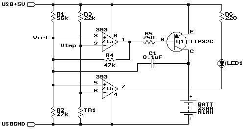
Widely available AA NiMH battery chargers are on the market, including those packaged to charge various battery types such as NiCd and NiCad. This project features a battery charger designed for two AA NiMH or NiCd cells of any capacity...

NiMH / Nicad Charger
I specifically designed this circuit to charge 2 batteries for my digital cameras, but it can be modified to charge 3, 4, 5, or more cells. However, it will not work with only one cell as that voltage is too...

USB Powered Stereo Computer Speaker
This is the circuit diagram of a USB-powered computer speaker, commonly referred to as multimedia speakers for PCs. The circuit features a single-chip design, operates on a low-voltage electrical power supply, is compatible with USB power from computers, and incorporates...

NiMh and NiCd Battery Charger Circuit
This automatic NiCd charger for 9V NiCd batteries utilizes the properties of a 555 timer and is straightforward to construct. The charger is designed to automatically maintain a full charge on the battery, allowing it to remain connected for extended...

v96 ghetto charger
Create a robotic team mascot for a workplace. The initial phase of this project involved designing a charger for the robot's batteries. The aim was to develop a charger compatible with various NiMH battery packs ranging from 700 mAh to...

Float Charger For NiMH Cells
Although not a new device, the LM317 is still a high-performance regulator. Its output voltage is essentially immune to fluctuations in load and supply voltage.
The LM317 is a versatile adjustable linear voltage regulator widely used in various electronic applications. It...