


1-Wire Two-way level converter unit (from 1.8V to 5V) Reference design
#1-Wire
#level converter
#voltage translation
#host computer
#reference design
#1.8V
#5V
#drain open
#IO framework

Description: The designer requires a 1-Wire host computer IO framework that operates at 1.8V. Most 1-Wire devices are unable to function at this voltage. This application recommends implementing a 1.8V 1-Wire host computer alongside a 5V 1-Wire reference design for level switching between devices. The MAX3394E level converter unit is suggested to facilitate this level switching. Common 1-Wire host computer devices include FPGA, microprocessors, DS2482-100, and DS2480B, with typical operating voltages ranging from 2.8V to 5.25V. Historically, 1-Wire host computers utilized a 5V logic level for device communication. The current design aims to provide a 1-Wire host computer IO that can manage a drain logic at 1.8V. While many 1-Wire devices can function at 5V, the majority do not operate at 1.8V, necessitating a two-way level converter to address this limitation. The reference design employs the Maxim MAX3394E two-way level converter, which features an 8-pin, 3mm x 3mm TDFN package. This unit is capable of driving significant capacitive loads, typically exceeding 500pF. The VCC I/O pin of the MAX3394E includes 15kV HBM (Human Body Model) electrostatic protection, ensuring safety for the 1-Wire host computer. The 1-Wire bus line connects to external devices, making HBM protection essential. It is recommended to use a pull-up resistor (R3) to enhance ESD protection, employing the DS9503P for improved safeguarding of the device. The schematic in Fig. 1 illustrates the implementation of the MAX3394E for transitioning from 1.8V to 5V with a two-way level switch. The circuit features a drain open port, with the I/O pins VL and VCC connected through 10k pull-up resistors. VL is set to 1.8V and VCC to 5.0V. CH1 represents the 1-Wire host computer (OW_MASTER), while CH2 denotes the DS1920 (OW_SLAVE), with a maximum OW_SLAVE line length of 2.4 meters. Testing was conducted at room temperature without selective pull-up resistors in Fig. 1. Fig. 2 shows the reset characteristics of the MAX3394E, where the pulse amplitude for online acknowledgment is less than 250mV, and the peak voltage remains below 0.4V, which is lower than the VIL threshold of the 1-Wire host computer. Fig. 5 presents the waveform for reading and operating the 1-Wire with the slave device, indicating that the drain open port recycles back to read a logic level of 0, with a maximum value lower than 0.4V, consistent with the VIL threshold of the 1-Wire host computer. This design is intended to facilitate a two-way level switch from 1.8V to 5V for typical 1-Wire devices, complete with a schematic circuit diagram, BOM, model, and test waveforms included in the introduction.
The 1-Wire protocol is a low-speed, half-duplex communication system that allows for multiple devices to be connected to a single data line. In this design, the MAX3394E serves as a crucial component, enabling seamless communication between devices operating at different voltage levels. The two-way level converter effectively translates the voltage levels between the 1.8V and 5V systems, ensuring compatibility and reliable data transmission.
The MAX3394E's design incorporates robust electrostatic discharge (ESD) protection, which is vital in environments where devices may be exposed to static electricity. The 15kV HBM rating ensures that the circuitry is safeguarded against damage from electrostatic discharge, enhancing the longevity and reliability of the system.
In practical applications, the circuit will be tested under various conditions to validate its performance. Parameters such as response time, signal integrity, and the ability to handle capacitive loads will be thoroughly examined. The incorporation of pull-up resistors is a standard practice in 1-Wire applications to ensure that the bus line is properly biased, facilitating reliable communication.
The testing phase will also involve measuring the voltage levels during operation, ensuring that the MAX3394E maintains the required voltage thresholds for both the master and slave devices. The design's success will depend on the careful selection of components, adherence to recommended practices, and thorough testing to ensure that the 1-Wire communication remains robust across varying environmental conditions.The designer requires 1 Wire host computer IO framework of adopting the drain and opening a way, work in 1. 8V. Majority 1 Wire is unable to work in 1. 8V from the device. Note of this application has recommended realizing 1. 8V 1 Wire host computer and 5V 1 Wire reference design RD from level switch between the devices. This is cons ulted and is designed to drive typical 1 Wire from the device, make use of MAX3394E level converter unit to realize level switch. FPGA, microprocessor, DS2482-100 and DS2480B are 1 common Wire host computer device. 1-Wire/iButton Produced from the device by Maxim, the typical working voltage of this serial devices is from 2.
8V to 5. 25V. In the past, 1 traditional Wire host computer and from the logic of adopting 5V drain to open a way of the device. Now, the designer needs 1 Wire host computer IO to offer the logic of opening a way of drain of 1. 8V. And the majority 1 Wire can work from the device in 5V Safety Ground, the overwhelming majority in them is unable to work in 1.
8V. Need a two-way level converter unit to overcome this kind of restriction. This reference design RD Adopt Maxim MAX3394E two-way level converter unit, use for solve the problem that in this kind of application. MAX3394E two-way level converter unit adopts 8 pins, 3mm x 3mm TDFN to capsulate. Rely on its reinforced circuit of internal pendulum rate, but is used in great condensive load to drive ideally.
1 Wire is usually greater than 500pF from the condensive load of the device. VCC I/O pin of MAX3394E has 15kV HBM Human Body Model Electrostatic protection, offer protection for 1 Wire host computer. 1 Wire bus line is usually used for connecting the external world, it is a basic demand that HBM protects.
Recommend pulling upward the resistance R3, selective to pull circuit and 1 Wire upward, use DS9503P so as to strengthen ESD, protect from the device while being better. Fig. 1 illustrated circuit make use of MAX3394E to realize from 1. 8V to the intersection of 5V and two-way level switch, system adopt drain open a way port. Fig. 1. 1- Wire two-way level from 1. 8V to 5V The schematic circuit diagram of the converter, be careful, the pin I/O VL and I/O VCC has 10k to pull upward.
VL =1. 8V VCC =5. 0V CH1: 1 Wire host computer OW_MASTER CH2: DS1920 OW_SLAVE OW_SLAVE line is long: 2. 4 meters, maximum value. Have not used in Fig. 1 selective and strongly and pulled while testing. Measure only at the room temperature. Fig. 2. Reset the characteristic that the waveform can find out MAX3394E from 1 Wire, the pulse amplitude of online acknowledgement is less than 250mV, 0. 4V peak voltage less than model 1 Wire host computer VIL. Fig. 5. 1- the intersection of Wire and waveform of reading, operating, 1- the intersection of Wire and the intersection of slave and drain open a way whom port recycle back to read 0 Time slot, level is lower than 0.
4V maximum value of model 1 Wire host computer VIL. This is consulted and is designed to realize from 1. 8V to 5V 1- Wire two-way level switch, drives typical 1 Wire from the device. Design setting up and test of the circuit, provide schematic circuit diagram, BOM and model and test the waveform in introduction to this text.
The 1-Wire protocol is a low-speed, half-duplex communication system that allows for multiple devices to be connected to a single data line. In this design, the MAX3394E serves as a crucial component, enabling seamless communication between devices operating at different voltage levels. The two-way level converter effectively translates the voltage levels between the 1.8V and 5V systems, ensuring compatibility and reliable data transmission.
The MAX3394E's design incorporates robust electrostatic discharge (ESD) protection, which is vital in environments where devices may be exposed to static electricity. The 15kV HBM rating ensures that the circuitry is safeguarded against damage from electrostatic discharge, enhancing the longevity and reliability of the system.
In practical applications, the circuit will be tested under various conditions to validate its performance. Parameters such as response time, signal integrity, and the ability to handle capacitive loads will be thoroughly examined. The incorporation of pull-up resistors is a standard practice in 1-Wire applications to ensure that the bus line is properly biased, facilitating reliable communication.
The testing phase will also involve measuring the voltage levels during operation, ensuring that the MAX3394E maintains the required voltage thresholds for both the master and slave devices. The design's success will depend on the careful selection of components, adherence to recommended practices, and thorough testing to ensure that the 1-Wire communication remains robust across varying environmental conditions.The designer requires 1 Wire host computer IO framework of adopting the drain and opening a way, work in 1. 8V. Majority 1 Wire is unable to work in 1. 8V from the device. Note of this application has recommended realizing 1. 8V 1 Wire host computer and 5V 1 Wire reference design RD from level switch between the devices. This is cons ulted and is designed to drive typical 1 Wire from the device, make use of MAX3394E level converter unit to realize level switch. FPGA, microprocessor, DS2482-100 and DS2480B are 1 common Wire host computer device. 1-Wire/iButton Produced from the device by Maxim, the typical working voltage of this serial devices is from 2.
8V to 5. 25V. In the past, 1 traditional Wire host computer and from the logic of adopting 5V drain to open a way of the device. Now, the designer needs 1 Wire host computer IO to offer the logic of opening a way of drain of 1. 8V. And the majority 1 Wire can work from the device in 5V Safety Ground, the overwhelming majority in them is unable to work in 1.
8V. Need a two-way level converter unit to overcome this kind of restriction. This reference design RD Adopt Maxim MAX3394E two-way level converter unit, use for solve the problem that in this kind of application. MAX3394E two-way level converter unit adopts 8 pins, 3mm x 3mm TDFN to capsulate. Rely on its reinforced circuit of internal pendulum rate, but is used in great condensive load to drive ideally.
1 Wire is usually greater than 500pF from the condensive load of the device. VCC I/O pin of MAX3394E has 15kV HBM Human Body Model Electrostatic protection, offer protection for 1 Wire host computer. 1 Wire bus line is usually used for connecting the external world, it is a basic demand that HBM protects.
Recommend pulling upward the resistance R3, selective to pull circuit and 1 Wire upward, use DS9503P so as to strengthen ESD, protect from the device while being better. Fig. 1 illustrated circuit make use of MAX3394E to realize from 1. 8V to the intersection of 5V and two-way level switch, system adopt drain open a way port. Fig. 1. 1- Wire two-way level from 1. 8V to 5V The schematic circuit diagram of the converter, be careful, the pin I/O VL and I/O VCC has 10k to pull upward.
VL =1. 8V VCC =5. 0V CH1: 1 Wire host computer OW_MASTER CH2: DS1920 OW_SLAVE OW_SLAVE line is long: 2. 4 meters, maximum value. Have not used in Fig. 1 selective and strongly and pulled while testing. Measure only at the room temperature. Fig. 2. Reset the characteristic that the waveform can find out MAX3394E from 1 Wire, the pulse amplitude of online acknowledgement is less than 250mV, 0. 4V peak voltage less than model 1 Wire host computer VIL. Fig. 5. 1- the intersection of Wire and waveform of reading, operating, 1- the intersection of Wire and the intersection of slave and drain open a way whom port recycle back to read 0 Time slot, level is lower than 0.
4V maximum value of model 1 Wire host computer VIL. This is consulted and is designed to realize from 1. 8V to 5V 1- Wire two-way level switch, drives typical 1 Wire from the device. Design setting up and test of the circuit, provide schematic circuit diagram, BOM and model and test the waveform in introduction to this text.

1-Wire Barometer Calibration
The resolution of the barometric pressure is approximately 0.00417 inHg (0.0139 kPa) within a pressure range of 31.0 to 28.0 inHg (105.0 to 95.0 kPa, or 1050 to 950 mb or hPa). Higher resolutions can be achieved with a narrower...

5volt power supply
This circuit is a small +5V power supply, which is useful when experimenting with digital electronics. Small inexpensive wall transformers with variable output voltage are available from any electronics shop and supermarket. Those transformers are easily available, but usually their...

5V - Digital Camera Charger
There is no need to be disappointed the next time your digital camera displays a low battery indication during a picnic trip. Simply connect this digital camera adapter to the cigarette lighter outlet of your car and link the camera...

5V Power Supply For On Train Radio Camera
A radio camera on a model railway is designed to transmit continuously while the train is in motion and to continue transmitting for a few minutes after the train stops. If the train starts moving again after a relatively long...

5V Regulated Power SupplyCircuit
This circuit is a compact +5V power supply that is beneficial for digital electronics experimentation. Inexpensive wall transformers with variable output voltage can be found at electronics shops and supermarkets. While these transformers are readily available, their voltage regulation is...

5V Regulated Power Supply
5V regulated power supply circuit, 5V power supply circuit, regulated power supply circuit diagram.
The 5V regulated power supply circuit is designed to provide a stable output voltage of 5 volts, which is essential for powering various electronic devices and circuits....
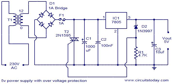
5V power supply with overvoltage protection
For circuits using TTL ICs, the supply voltage is a significant concern, as even a slight increase from the rated 5V can damage the IC. Relying solely on fuses is insufficient since a fuse may take several milliseconds to blow,...

5V 0.5A power supply
The circuit functions as a constant voltage source, modified by feedback components R2 and R3 to maintain a stable output voltage. The ZN424E output must be at least 2 volts above the negative rail, with the load connected to the...

5V to 2.5V voltage regulator circuit
A 5V to 2.5V voltage regulator circuit is designed for use in computer motherboards. At its core, this circuit utilizes the RT9202 power management chip. The RT9202 functions as a switching pulse generating circuit, which, upon startup, converts a 5V...