


Doorphone Intercom schematic

Description: In this doorphone circuit, an 8 ohm speaker is used both as a microphone and also an output device. The BC109C stage amplifies in common base mode, giving good voltage gain, whilst providing a low impedance input to match the speaker. Self DC bias is used allowing for variations in transistor current gain. More: An LM386 is used in non-inverting mode as a power amplifier to boost voltage gain and drive the 8 ohm speaker. The 10k potentiometer acts as the volume control, and overall gain may be adjusted using the 5k preset. The double pole double throw switch, rev
The doorphone circuit operates by utilizing an 8-ohm speaker for dual functionality, serving as both a microphone and an audio output device. The circuit begins with the BC109C transistor, configured in a common base mode, which is advantageous for providing a high voltage gain while ensuring a low impedance input. This configuration is essential as it effectively matches the impedance of the 8-ohm speaker, facilitating efficient signal transfer.
The self DC biasing technique employed in the BC109C stage is designed to accommodate variations in the transistor's current gain, ensuring stable operation across different conditions. This feature is critical for maintaining consistent performance in various environmental scenarios, which may affect the transistor's characteristics.
Following the initial amplification stage, an LM386 power amplifier is integrated into the circuit in a non-inverting configuration. This component is pivotal for further boosting the voltage gain, enabling the circuit to drive the 8-ohm speaker effectively. The LM386 is known for its low power consumption and ability to deliver sufficient output power, making it suitable for battery-operated devices like doorphones.
Volume control is achieved through a 10k potentiometer, allowing users to adjust the audio output level according to their preferences. Additionally, a 5k preset resistor is included in the design to provide further adjustments to the overall gain of the circuit, facilitating fine-tuning of the audio performance.
The circuit also incorporates a double pole double throw (DPDT) switch, which serves to select between different operational modes or to engage/disengage specific components of the circuit as needed. This flexibility enhances the functionality of the doorphone, allowing it to adapt to various usage scenarios.
Overall, the design of this doorphone circuit emphasizes efficient audio processing and user control, ensuring a reliable communication solution.In this doorphone circuit,an 8 ohm speaker is used both as a microphone and also an output device. The BC109C stage amplifies in common base mode, giving good voltage gain , whilst providing a low impedance input to match the speaker. Self DC bias is used allowing for variations in transistor current gain. An LM386 is used in non-inverting mode as a power amplifier to boost voltage gain and drive the 8 ohm speaker. The 10k potentiometer acts as the volume control, and overall gain may be adjusted using the 5k preset.
The double pole double throw switch, rev
The doorphone circuit operates by utilizing an 8-ohm speaker for dual functionality, serving as both a microphone and an audio output device. The circuit begins with the BC109C transistor, configured in a common base mode, which is advantageous for providing a high voltage gain while ensuring a low impedance input. This configuration is essential as it effectively matches the impedance of the 8-ohm speaker, facilitating efficient signal transfer.
The self DC biasing technique employed in the BC109C stage is designed to accommodate variations in the transistor's current gain, ensuring stable operation across different conditions. This feature is critical for maintaining consistent performance in various environmental scenarios, which may affect the transistor's characteristics.
Following the initial amplification stage, an LM386 power amplifier is integrated into the circuit in a non-inverting configuration. This component is pivotal for further boosting the voltage gain, enabling the circuit to drive the 8-ohm speaker effectively. The LM386 is known for its low power consumption and ability to deliver sufficient output power, making it suitable for battery-operated devices like doorphones.
Volume control is achieved through a 10k potentiometer, allowing users to adjust the audio output level according to their preferences. Additionally, a 5k preset resistor is included in the design to provide further adjustments to the overall gain of the circuit, facilitating fine-tuning of the audio performance.
The circuit also incorporates a double pole double throw (DPDT) switch, which serves to select between different operational modes or to engage/disengage specific components of the circuit as needed. This flexibility enhances the functionality of the doorphone, allowing it to adapt to various usage scenarios.
Overall, the design of this doorphone circuit emphasizes efficient audio processing and user control, ensuring a reliable communication solution.In this doorphone circuit,an 8 ohm speaker is used both as a microphone and also an output device. The BC109C stage amplifies in common base mode, giving good voltage gain , whilst providing a low impedance input to match the speaker. Self DC bias is used allowing for variations in transistor current gain. An LM386 is used in non-inverting mode as a power amplifier to boost voltage gain and drive the 8 ohm speaker. The 10k potentiometer acts as the volume control, and overall gain may be adjusted using the 5k preset.
The double pole double throw switch, rev

Low-Cost and Simple Intercom
This is a low-cost and simple intercom circuit design that utilizes three transistors. Even a novice can assemble it on a piece of veroboard without difficulty.
The intercom circuit is designed to facilitate two-way audio communication between two locations. The core...

Simplest Intercom
This circuit was requested by a school teacher. It is a simple intercom that anyone can assemble and operate. It is based on the LM380 integrated circuit (IC).
The intercom circuit utilizing the LM380 IC is designed for straightforward assembly and...

Speaker Microphone Circuit
This circuit allows the use of an inexpensive loudspeaker as a microphone. Sound waves that reach the speaker cone create fluctuations in the voice coil. The movement of the voice coil within the speaker's magnetic field generates a small electrical...

Schematics Stereo Parabolic Microphone
The mini condenser microphone converts sounds into an electrical signal. Resistor R1 provides bias for the condenser microphone's internal amplifier transistor. The 2N3906 PNP transistor acts as a low-noise microphone input amplifier. The 10K gain potentiometer is used for adjusting...

simple mic amplifier
Schematic and description of a simple microphone amplifier circuit. This circuit contains two stages: the first is a microphone preamplifier, and the second is an audio amplifier using the LM386 Amplifier IC.
The simple microphone amplifier circuit is designed to amplify...
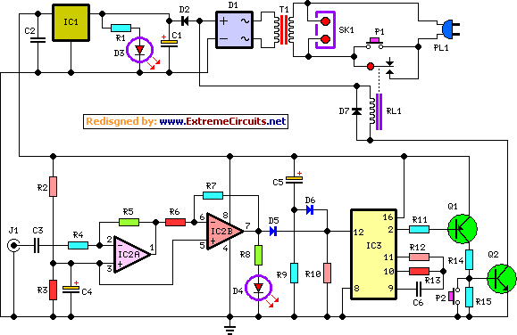
amplifier timer circuit schematic
This circuit deactivates an amplifier or any connected device when a low-level audio signal at its input is absent for at least 15 minutes. By pressing P1, the device is powered on, supplying power to any appliance connected to SK1....
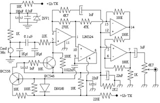
mic audio circuit
This circuit can be utilized in intercom systems, walkie-talkies, low-power transmitters, and packet radio receivers. Transistors T1 and T2 constitute the microphone preamplifier. Resistor R1 provides the necessary bias for the condenser microphone, while preset VR1 serves as a gain...

Room Monitor Circuit
The circuit utilizes Q1 to buffer the right-channel balance output, while Q2 and Q3 create a VOX circuit. When the microphone signal level increases, the VOX output also rises, causing the multiplexer within IC1 to route the high-gain left-channel output...

Emitter negative feedback differential amplifier gain control circuit
A controllable gain amplifier functions as an automatic gain control circuit within the execution unit. The primary methods for controlling the amplifier's gain involve two approaches: one is by adjusting certain parameters of the amplifier itself, such as emitter current,...