


Improving USB 2.0 Switched-System Response
#USB 2.0
#inductors
#capacitance
#MAX4906EF
#signal integrity
#high-frequency
#circuit tuning
#eye opening
#240 MHz
#500 MHz

Description: By incorporating discrete inductors in series with the device, it is possible to "tune out" some of the capacitance and enhance the eye opening. By adding sufficient inductance to peak the third harmonic at 240 MHz, while considering the capacitance of the device and any additional board capacitance, the lower frequencies will remain largely unaffected, thus improving performance where it is most needed. Assuming that the MAX4906EF and the added board capacitance total 12 pF, a small amount of series inductance can effectively peak the response at 500 MHz.
To optimize the performance of high-frequency circuits, the integration of discrete inductors in series with a device serves as a practical approach to managing capacitance. The primary objective is to fine-tune the circuit by selectively enhancing the response at specific frequencies, particularly the third harmonic. In this context, the MAX4906EF is utilized alongside additional board capacitance, which is estimated to be 12 pF.
The tuning process involves calculating the required inductance to achieve a peak response at 500 MHz. Given that the third harmonic of 240 MHz corresponds to a frequency of 720 MHz, the application of series inductance allows for the adjustment of the resonant frequency of the circuit. The formula for resonant frequency (f_r) in an LC circuit is given by:
f_r = 1 / (2π√(LC))
Where L is the inductance and C is the total capacitance. By rearranging this equation, it is possible to determine the necessary inductance to achieve the desired frequency response.
The choice of inductor value will be critical; it must be sufficient to counteract the capacitance without significantly affecting lower frequency signals. This selective tuning enhances the eye opening, which is crucial for high-speed digital signals, allowing for better signal integrity and reduced bit error rates.
In practical applications, the inductor should be chosen based on its quality factor (Q), as a higher Q will result in lower losses and better performance at the target frequency. Additionally, layout considerations should be taken into account to minimize parasitic capacitances and inductances that could adversely affect the circuit's performance.
Overall, this methodology provides a robust solution for enhancing the performance of high-frequency circuits while maintaining the integrity of lower frequency signals.By adding discrete inductors in series with the device, we can œtune out some of the capacitance, and improve the eye opening. If we add enough inductance to peak the 3rd harmonic of 240 MHz, with the capacitance of the device and any added board capacitance, we won t affect the lower frequencies much, and we ll enhance the performance where we need it.
If we assume that the MAX4906EF and the added board capacitance amounts to 12 pf, and we d like to peak the response at 500 MHz, then a small amount of series inductance will do just that..
To optimize the performance of high-frequency circuits, the integration of discrete inductors in series with a device serves as a practical approach to managing capacitance. The primary objective is to fine-tune the circuit by selectively enhancing the response at specific frequencies, particularly the third harmonic. In this context, the MAX4906EF is utilized alongside additional board capacitance, which is estimated to be 12 pF.
The tuning process involves calculating the required inductance to achieve a peak response at 500 MHz. Given that the third harmonic of 240 MHz corresponds to a frequency of 720 MHz, the application of series inductance allows for the adjustment of the resonant frequency of the circuit. The formula for resonant frequency (f_r) in an LC circuit is given by:
f_r = 1 / (2π√(LC))
Where L is the inductance and C is the total capacitance. By rearranging this equation, it is possible to determine the necessary inductance to achieve the desired frequency response.
The choice of inductor value will be critical; it must be sufficient to counteract the capacitance without significantly affecting lower frequency signals. This selective tuning enhances the eye opening, which is crucial for high-speed digital signals, allowing for better signal integrity and reduced bit error rates.
In practical applications, the inductor should be chosen based on its quality factor (Q), as a higher Q will result in lower losses and better performance at the target frequency. Additionally, layout considerations should be taken into account to minimize parasitic capacitances and inductances that could adversely affect the circuit's performance.
Overall, this methodology provides a robust solution for enhancing the performance of high-frequency circuits while maintaining the integrity of lower frequency signals.By adding discrete inductors in series with the device, we can œtune out some of the capacitance, and improve the eye opening. If we add enough inductance to peak the 3rd harmonic of 240 MHz, with the capacitance of the device and any added board capacitance, we won t affect the lower frequencies much, and we ll enhance the performance where we need it.
If we assume that the MAX4906EF and the added board capacitance amounts to 12 pf, and we d like to peak the response at 500 MHz, then a small amount of series inductance will do just that..

Capacitance-meter
U1a serves as an oscillator, while U1b functions as the measurement component of the circuit. It converts an unknown capacitance into a pulse-width modulated signal, similar to the operation of an automotive dwell meter. The meter is linear, meaning that...

Capacitance multiplier
The circuit can be utilized to simulate large capacitances using components of smaller values. With the specified values and a capacitance of 10 µF, an effective capacitance of 10,000 µF was achieved. The quality factor (Q) is constrained by the...

Capacitance meter
This project is exactly what you need. It is simple to construct and can be connected to almost any analogue multimeter. The scales are accurate over each range - certainly good enough to provide you with the value of any...

Wide-band high-frequency electric field strength meter schematic
This is a simple and low-cost broadband high-frequency electric field strength meter. The field strength of the radio signal is converted into a DC measurement for analysis. The signal is captured by a coil and processed through a diode (D1)....

capacity Computing Current from known Capacitance and Time to Charge to Known Voltage
Consider a capacitor with capacitance C that charges to a voltage V and discharges to 0V at a frequency of 5 times per second. To estimate the average current, also referred to as the RMS current, a rough approximation can...
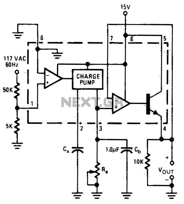
Capacitance meter
The output voltage is proportional to the capacitance connected to pin 2 of the charge pump. The meter operates over a capacitance range of 0.1 to 0 µF with a set resistance of 111 kΩ. Within this capacitance range, the...

No-bias L-C High-Frequency Oscillator
This oscillator does not require biasing components. Only an inductor and various matching or tuning capacitors are needed to set the operating frequency. The active component is the 74HCU04 hex inverter, with only one of the six inverters necessary for...

Capacitor Meter Circuit
The circuit consists of an oscillator with variable frequency, a frequency divider, and a measurement stage. The oscillator is based on an inverter from a 74HC14 and generates a frequency that is inversely proportional to the capacitance of the capacitor...

A capacitance measuring circuit
A capacitive measuring instrument is a direct reading device that measures the capacitance of a circuit. This instrument is capable of measuring capacitance values ranging from a few picofarads to 0.1 microfarads, with specific ranges of 25 pF, 100 pF,...