


lm1893 power line modem circuit
#LM1893
#power line communication
#half-duplex
#serial communication
#modem
#data transfer
#remote communication
#power mains
#bit stream
#interface

Description: This circuit is designed for an LM1893 power line modem, which facilitates information transfer between remote locations using the power mains. The LM1893 serves as a power line interface for half-duplex (bi-directional) communication of serial bit streams employing various coding methods. To maximize range, an impulse noise filter and a PLL-based demodulator are integrated for reception. During transmission, a sinusoidal carrier is applied and frequency-shift keying (FSK) modulation is utilized on the power line through a robust on-chip driver. In addition to the LM1893, the circuit incorporates a COPS controller and various discrete components.
The LM1893 power line modem circuit operates by utilizing the existing electrical wiring to transmit and receive data, effectively turning the power lines into a communication medium. The half-duplex nature of the communication allows for data to be sent and received, albeit not simultaneously, which is suitable for many applications where full-duplex communication is not critical.
The design includes essential elements such as an impulse noise filter that mitigates interference from electrical noise present on the power lines, ensuring clearer signal reception. The integrated phase-locked loop (PLL) demodulator enhances signal integrity by locking onto the carrier frequency, thus enabling precise extraction of the modulated data signal.
For the transmission side, the circuit applies a sinusoidal carrier wave that provides the necessary frequency for FSK modulation. This modulation technique allows the encoding of digital information onto the carrier wave by varying its frequency, which is particularly effective in noisy environments typical of power line communications. The rugged on-chip driver ensures that the signal can be transmitted over long distances without significant degradation.
The inclusion of a COPS controller allows for additional processing capabilities, enabling the system to handle various control tasks and improve overall functionality. The discrete components in the circuit complement the LM1893 and COPS controller, providing necessary support for filtering, amplification, and signal conditioning.
Overall, this circuit exemplifies a robust solution for power line communication, leveraging existing infrastructure to facilitate data transfer, making it a versatile choice for remote communication applications.This is a circuit for an LM1893 power line modem circuit. This circuit is used to transfer information between remote location by using the power mains. This circuit uses LM1893 that is used as a power line interface for half-duplex (bi-directional) communication of serial bit stream of virtually any coding. This is the figure of the circuit; To g ive maximum range, impulse noise filter and a PLL-based demodulator are combined in reception. In transmission, a sinusoidal carrier is impressed and FSK modulated on most any power line via rugged on-chip driver. Besides LM1893, this circuit also uses a COPS controller and discrete components. [Circuit schematic source: National Semiconductor Notes]
The LM1893 power line modem circuit operates by utilizing the existing electrical wiring to transmit and receive data, effectively turning the power lines into a communication medium. The half-duplex nature of the communication allows for data to be sent and received, albeit not simultaneously, which is suitable for many applications where full-duplex communication is not critical.
The design includes essential elements such as an impulse noise filter that mitigates interference from electrical noise present on the power lines, ensuring clearer signal reception. The integrated phase-locked loop (PLL) demodulator enhances signal integrity by locking onto the carrier frequency, thus enabling precise extraction of the modulated data signal.
For the transmission side, the circuit applies a sinusoidal carrier wave that provides the necessary frequency for FSK modulation. This modulation technique allows the encoding of digital information onto the carrier wave by varying its frequency, which is particularly effective in noisy environments typical of power line communications. The rugged on-chip driver ensures that the signal can be transmitted over long distances without significant degradation.
The inclusion of a COPS controller allows for additional processing capabilities, enabling the system to handle various control tasks and improve overall functionality. The discrete components in the circuit complement the LM1893 and COPS controller, providing necessary support for filtering, amplification, and signal conditioning.
Overall, this circuit exemplifies a robust solution for power line communication, leveraging existing infrastructure to facilitate data transfer, making it a versatile choice for remote communication applications.This is a circuit for an LM1893 power line modem circuit. This circuit is used to transfer information between remote location by using the power mains. This circuit uses LM1893 that is used as a power line interface for half-duplex (bi-directional) communication of serial bit stream of virtually any coding. This is the figure of the circuit; To g ive maximum range, impulse noise filter and a PLL-based demodulator are combined in reception. In transmission, a sinusoidal carrier is impressed and FSK modulated on most any power line via rugged on-chip driver. Besides LM1893, this circuit also uses a COPS controller and discrete components. [Circuit schematic source: National Semiconductor Notes]

Modem shutdown Indicator
The circuit is designed for individuals who spend extensive hours exploring the various resources of this site. Although it comprises only three components, it effectively indicates whether the telephone line has been released after a prolonged connection via modem to...

KD2BD Pacsat Modem
The KD2BD Pacsat Modem is a cost-effective, high-performance 1200 bps BPSK modem designed to connect a packet radio terminal node controller (TNC) with an amateur satellite ground station, enabling full-duplex access to the 1200 baud "Pacsat" constellation of amateur satellites....

Utah T1-Rate Modem
This page provides information about the T1-rate modem designed in 1993. It is important to note that this modem is primarily useful for licensed amateur radio operators and is not suitable for general use unless operated over wires, as it...

DS Protocol (Data transfer via handshake)
The DS protocol was designed to provide firmware-based bidirectional host-to-slave interprocessor communications for situations in which no hardware solution is available and the host and/or the slave is incapable of tending the interface in real time. The only specialized hardware...

BayComm packet modem
Ensure the correct 9-pin D-type connector is used so that the pins fit properly into the board. The two outer mounting holes for the 9-pin D-type connector should have a diameter of 3mm, while the holes for the pins should...

MF10 Full Duplex Modem Filter Diagram Schematic and Applications
Later, there will be applications including a Basic Circuit Description, Block Diagram of the MF10, Programmable Dual Clock Generator, Butterworth Lowpass Filter, MF10 as an Input Filter and Sample/Hold, Generating Quadrature Sine Waves, and the Non-Inverting Integrator used in the...
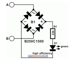
Modem Off Indicator
The modem off indicator is designed specifically for avid Internet users. It is evident that the circuit for this indicator is quite simple.
The modem off indicator serves a crucial function for users who rely heavily on internet connectivity. This circuit...

Suunto PC Interface
This page contains GIF images of the circuit diagram for the Solution interface, the PCB artwork, the board layout, a typical side elevation of the assembly, a parts list, some hints, and a brief overview of troubleshooting. This is a...

Data Transfer interface
The DS protocol was designed to provide firmware-based bidirectional host-to-slave inter-processor communications for situations in which no hardware solution is available and the host and/or the slave is incapable of tending the interface in real-time. The only specialized hardware required...