


NMEA 2000 CAN Marine Interface
#CAN Bus
#NMEA 2000
#marine interface
#data frame
#serial communication
#asynchronous transmission
#binary interchange
#transmitter
#receiver
#control field

Description: The CAN Bus interface utilizes an asynchronous transmission scheme that is regulated by start and stop bits at the beginning and end of each character. This interface operates using serial binary interchange, allowing information to be transmitted from transmitters to receivers in a data frame. The data frame consists of an Arbitration field, Control field, Data field, CRC field, and ACK field. It begins with a Start of Frame (SOF) and concludes with an End of Frame (EOF) space. The data field can range from 0 to 8 bits. The frame check sequence is calculated using a Cyclic Redundancy Code (CRC), with coefficients generated using modulo-2 arithmetic: X^15 + X^14 + X^10 + X^8 + X^7 + X^4 + X^3 + 1. The CAN protocol incorporates five error detection mechanisms: three at the message level and two at the bit level, which also includes error flags. At the message level, the mechanisms include Cyclic Redundancy Checks (CRC), Frame Checks, and Acknowledgment Error Checks. At the bit level, the methods used are Bit Monitoring and Bit Stuffing.
The CAN Bus (Controller Area Network) interface is a robust vehicle bus standard designed for real-time communication among microcontrollers and devices without a host computer. The asynchronous nature of the transmission allows for efficient data transfer, particularly in environments with high electrical noise, such as automotive applications.
The structure of the data frame is crucial for ensuring reliable communication. The Arbitration field is used to determine which node has the highest priority to transmit data when multiple nodes attempt to send messages simultaneously. The Control field specifies the type of data being sent, while the Data field carries the actual information, which can vary in length from 0 to 8 bytes, depending on the application requirements.
The CRC field plays a vital role in maintaining data integrity by detecting errors that may occur during transmission. The polynomial used in the CRC calculation is designed to provide a high level of error detection capability. The acknowledgment (ACK) field allows the receiving node to confirm successful receipt of the message, thereby enhancing the reliability of the communication process.
Error detection in the CAN protocol is comprehensive. At the message level, CRC checks ensure that the data has not been corrupted during transmission. Frame checks verify the integrity of the entire message format, while acknowledgment checks confirm that the intended recipient has received the data. At the bit level, Bit Monitoring ensures that the transmitted bits conform to expected values, while Bit Stuffing prevents long sequences of identical bits that could lead to synchronization issues.
Overall, the CAN Bus interface is a highly effective communication protocol that provides a reliable method for data exchange in complex systems, particularly in automotive and industrial applications. Its sophisticated error detection mechanisms and structured data frame format contribute to its widespread adoption in various electronic systems.The CAN Bus interface uses an asynchronous transmission scheme controlled by start and stop bits at the beginning and end of each character. This interface is used, employing serial binary interchange. Information is passed from transmitters to receivers in a data frame. The data frame is composed of an Arbitration field, Control field, Data field , CRC field, ACK field. The frame begins with a `Start of frame` [SOF], and ends with an `End of frame` [EOF] space. The data field may be from 0 to 8 bits. The frame check sequence is derived from a Cyclic Redundancy Code (CRC); the coefficients are generated modulo-2: X15 + X14 + X10 + X8 + X7 + X4 + X3 + 1. CAN implements five error detection mechanisms; 3 at the message level and 2 at the bit level [Also incorporates error flags].
At the message level: Cyclic Redundancy Checks (CRC), Frame Checks, Acknowledgment Error Checks. At the bit level: Bit Monitoring, Bit Stuffing.
The CAN Bus (Controller Area Network) interface is a robust vehicle bus standard designed for real-time communication among microcontrollers and devices without a host computer. The asynchronous nature of the transmission allows for efficient data transfer, particularly in environments with high electrical noise, such as automotive applications.
The structure of the data frame is crucial for ensuring reliable communication. The Arbitration field is used to determine which node has the highest priority to transmit data when multiple nodes attempt to send messages simultaneously. The Control field specifies the type of data being sent, while the Data field carries the actual information, which can vary in length from 0 to 8 bytes, depending on the application requirements.
The CRC field plays a vital role in maintaining data integrity by detecting errors that may occur during transmission. The polynomial used in the CRC calculation is designed to provide a high level of error detection capability. The acknowledgment (ACK) field allows the receiving node to confirm successful receipt of the message, thereby enhancing the reliability of the communication process.
Error detection in the CAN protocol is comprehensive. At the message level, CRC checks ensure that the data has not been corrupted during transmission. Frame checks verify the integrity of the entire message format, while acknowledgment checks confirm that the intended recipient has received the data. At the bit level, Bit Monitoring ensures that the transmitted bits conform to expected values, while Bit Stuffing prevents long sequences of identical bits that could lead to synchronization issues.
Overall, the CAN Bus interface is a highly effective communication protocol that provides a reliable method for data exchange in complex systems, particularly in automotive and industrial applications. Its sophisticated error detection mechanisms and structured data frame format contribute to its widespread adoption in various electronic systems.The CAN Bus interface uses an asynchronous transmission scheme controlled by start and stop bits at the beginning and end of each character. This interface is used, employing serial binary interchange. Information is passed from transmitters to receivers in a data frame. The data frame is composed of an Arbitration field, Control field, Data field , CRC field, ACK field. The frame begins with a `Start of frame` [SOF], and ends with an `End of frame` [EOF] space. The data field may be from 0 to 8 bits. The frame check sequence is derived from a Cyclic Redundancy Code (CRC); the coefficients are generated modulo-2: X15 + X14 + X10 + X8 + X7 + X4 + X3 + 1. CAN implements five error detection mechanisms; 3 at the message level and 2 at the bit level [Also incorporates error flags].
At the message level: Cyclic Redundancy Checks (CRC), Frame Checks, Acknowledgment Error Checks. At the bit level: Bit Monitoring, Bit Stuffing.
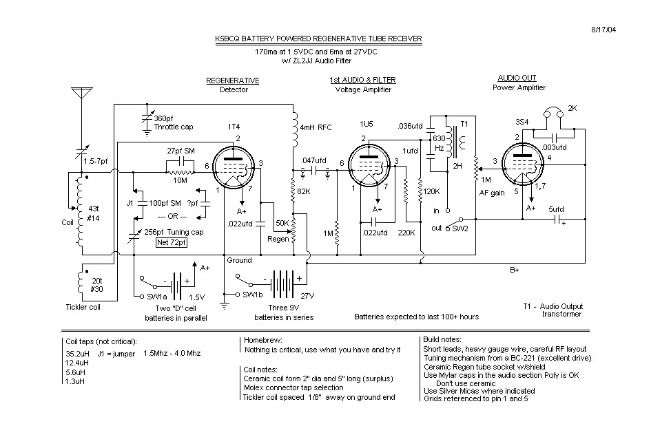
Battery Powered Tube Regenerative Receiver
The basic regenerative design is quite common. Before the schematic is created, there is a "concept stage," followed by the "available components stage," returning to the "concept stage," then moving on to the "mechanical/electrical layout stage," and finally sketching a...

Beacon-transmitter
This transmitter is suitable for transmitter hunts, remote key finding, or radio telemetry in model rockets. It can be tuned to the two-meter band or other VHF bands by adjusting capacitor C1 and inductor L1. L1 consists of four turns...

1-2 MHz radio transmitter circuit diagram
A circuit diagram of the T1 is a low-impedance output transformer, featuring a 5000-8 ohm resistor.
The T1 low-impedance output transformer is designed to match the output of audio amplifiers to the impedance of loudspeakers, ensuring optimal power transfer and minimal...
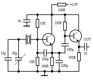
80M
This 80M receiver design incorporates the necessary switching mechanisms to enable the SSB filter and first intermediate frequency (I.F.) amplifier to function for transmission purposes. The receiver stages, from the radio frequency (R.F.) input to the speaker output, will be...

wireless headphones transmitter
This wireless headphone transmitter ensures a reliable connection over a distance of 2 meters. The oscillator frequency ranges between 1750 KHz and 3500 KHz, utilizing a ferrite bar as the antenna. IC1 amplifies the audio signal, while TC1 serves as...

A8V W8EXI 6CL6 One Tube Transmitter
A8V W8EXI 6CL6 One Tube Transmitter. The operation of the 6CL6 transmitter is actually quite sophisticated.
The A8V W8EXI 6CL6 One Tube Transmitter is a compact and efficient radio frequency (RF) transmitter that utilizes a single 6CL6 vacuum tube for its...

G0MRF 29.45 MHz Receiver Project
In 2007 and 2008, AMSAT-UK dedicated significant effort to a proposal for the European Space Agency (ESA) to include an Amateur Radio payload on the mass dummy during the maiden flight of the VEGA launcher. This initiative was referred to...
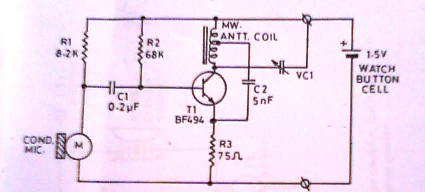
ultra miniature transmitter
This transmitter is approximately the size of a large coat button. It accepts direct voice input and operates on a single watch-type button cell, providing several tens of hours of use. The schematic illustrates that this transmitter is likely the...

80 Watt stereo transmitter
This transmitter was designed from the ground up to provide very high sound quality, coupled with excellent frequency stability, reliability, etc. It can be used as a standalone transmitter to serve a medium-sized town, or as an exciter to drive...