


Simple Two Way Communication Intercom Circuit Schematic diagram
#intercom
#two-way communication
#amplifier
#LM384
#loudspeakers
#switches
#audio
#simple circuit
#communication system

Description: An intercom or intercommunication circuit is a two-way communication system that provides a reliable communication line and is easy to implement. The circuit consists of an amplifier, two switches, and two loudspeakers, allowing for the extension of the system by adding more speakers with the help of additional switches. The IC LM384 functions as a power output amplifier in this intercom circuit, delivering approximately 2 watts of audio power with a 15-volt supply voltage. This intercom circuit diagram is simple and practical, suitable for home and office intercom applications. When switch S1 is in the "Talk" position, L1 operates as a microphone, while in the "Listen" position, L1 acts as a speaker. The same functionality applies to L2. The IC NE5534 serves as a preamplifier, enhancing the audio signal before it is fed into the LM384 amplifier section. The gain of the LM384 operational amplifier is set to 11. By adjusting the switch positions of S2 to "Talk" and S1 to "Listen," L2 connects to the input section while L1 connects to the output section.
The intercom circuit operates on a dual-channel basis, allowing users to communicate in both directions. The core components include the LM384 and NE5534 integrated circuits, which are critical for audio processing. The LM384, known for its ability to deliver significant audio power, is ideal for driving loudspeakers in intercom applications. Its output power capability, combined with a 15-volt power supply, ensures that the audio signal remains strong and clear.
The NE5534 preamplifier plays a vital role by boosting the audio signal before it reaches the LM384. This preamplification is crucial for maintaining audio fidelity, especially in environments with background noise. The gain setting of 11 for the LM384 ensures that the output signal is sufficiently amplified for clear communication.
The use of switches S1 and S2 allows for seamless toggling between talking and listening modes. This design enables each loudspeaker to function as both a microphone and a speaker, depending on the switch configuration. The ability to add more speakers enhances the system's versatility, making it suitable for various applications, from small residential setups to larger office environments.
Overall, the intercom circuit is a straightforward yet effective solution for two-way communication, leveraging the capabilities of the LM384 and NE5534 to deliver reliable audio performance. The design simplicity and scalability make it an attractive option for users seeking an efficient intercom system.Intercom or Inter communication circuit is a two directional communication system. It provides a reliable communication line and is extremely easy to implement. The circuit is prepared by an amplifier, two switches and two loudspeakers. We can extend this circuit by adding more number of speakers with the help of switches. IC LM384 works as a powe r output amplifier in this intercom circuit. LM384 provides almost 2 watts of audio power via 15 volts supply voltage. This intercom circuit diagram is very simple and practical circuit capable of using intercoms for homes, office intercom. If switch S1 is in Talk` contact, L1 functions as a Microphone. If it is in Listen` position, L1 functions as a Speaker. (Similar case applicable in L2 also. ) IC NE5534 works as a Pre Amplifier which boosts the Audio signal before applying to the LM384 amplifier section.
The gain of the LM384 op amp amplifier is set to 11. By changing the switch positions of S2 in to Talk` position and S1 to Listen` position, L2 get connected to the input section and L1 connected to output section.
The intercom circuit operates on a dual-channel basis, allowing users to communicate in both directions. The core components include the LM384 and NE5534 integrated circuits, which are critical for audio processing. The LM384, known for its ability to deliver significant audio power, is ideal for driving loudspeakers in intercom applications. Its output power capability, combined with a 15-volt power supply, ensures that the audio signal remains strong and clear.
The NE5534 preamplifier plays a vital role by boosting the audio signal before it reaches the LM384. This preamplification is crucial for maintaining audio fidelity, especially in environments with background noise. The gain setting of 11 for the LM384 ensures that the output signal is sufficiently amplified for clear communication.
The use of switches S1 and S2 allows for seamless toggling between talking and listening modes. This design enables each loudspeaker to function as both a microphone and a speaker, depending on the switch configuration. The ability to add more speakers enhances the system's versatility, making it suitable for various applications, from small residential setups to larger office environments.
Overall, the intercom circuit is a straightforward yet effective solution for two-way communication, leveraging the capabilities of the LM384 and NE5534 to deliver reliable audio performance. The design simplicity and scalability make it an attractive option for users seeking an efficient intercom system.Intercom or Inter communication circuit is a two directional communication system. It provides a reliable communication line and is extremely easy to implement. The circuit is prepared by an amplifier, two switches and two loudspeakers. We can extend this circuit by adding more number of speakers with the help of switches. IC LM384 works as a powe r output amplifier in this intercom circuit. LM384 provides almost 2 watts of audio power via 15 volts supply voltage. This intercom circuit diagram is very simple and practical circuit capable of using intercoms for homes, office intercom. If switch S1 is in Talk` contact, L1 functions as a Microphone. If it is in Listen` position, L1 functions as a Speaker. (Similar case applicable in L2 also. ) IC NE5534 works as a Pre Amplifier which boosts the Audio signal before applying to the LM384 amplifier section.
The gain of the LM384 op amp amplifier is set to 11. By changing the switch positions of S2 in to Talk` position and S1 to Listen` position, L2 get connected to the input section and L1 connected to output section.

Audio Booster
The circuit diagram represents a booster for an audio application. It features a linear potentiometer R5 with a resistance of 100K ohms, which includes an on/off switch. The capacitor C1 should be selected with a value between 0.05 µF and...
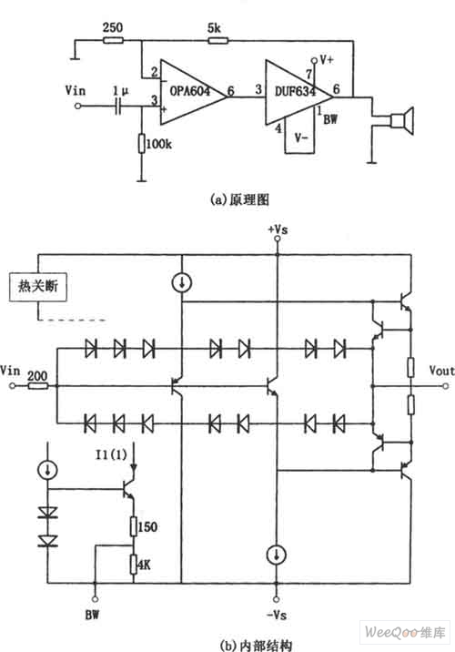
OPA604 High Performance and Small Power Audio Amplifier
The provided image depicts a high-performance and low-power audio power amplifier circuit. The initial stage utilizes the MOSFET hi-fi operational amplifier OPA604, while the subsequent stage employs the high-speed buffer BUF634. Voltage series negative feedback is implemented between the two...

Two way intercom circuit diagram using transistors and UM66 as ringer
A straightforward intercom circuit designed using transistors. It does not require a changeover switch and can be used similarly to a telephone.
This intercom circuit utilizes transistors to facilitate communication between two or more stations without the need for complex switching...

Low-Cost and Simple Intercom
This is a low-cost and simple intercom circuit design. Some intercom circuits are built using integrated circuits. The circuit described here utilizes three readily available transistors that can be easily found in electronic stores. Even a novice can assemble it.
The...

A simple and effective short-wave antenna amplifier circuit
This amplifier is designed for outdoor installation and is connected to an indoor power line box. It utilizes either 50-ohm or 75-ohm coaxial cables for the connection between indoor and outdoor units. The amplifier circuit board is depicted in Figures...

Low-Cost and Simple Intercom
This is a low-cost and simple intercom circuit design that utilizes three transistors. Even a novice can assemble it on a piece of veroboard without difficulty.
The intercom circuit is designed to facilitate two-way audio communication between two locations. The core...

headphone monitor amp
This simple amplifier is designed to add a headphone jack to equipment that does not have this feature. The Headphone Buffer circuit board is compact (1.2" x 1.4"), allowing it to fit into even the smallest spaces, and its low...

Audio Simple Sound-to-Light Converter Schematic Diagram
Figure 1 illustrates a simple circuit designed for converting an audio signal (such as one from the output terminals of a CD player). The circuit primarily consists of a buffer/amplifier stage and three filtering circuits: a high-pass filter, a band-pass...

BRIDGED T AUDIO OSCILLATOR
This circuit incorporates heavy degenerative feedback, utilizing a small lamp as a nonlinear compensating resistance. It provides a constant output frequency and voltage for supply voltages ranging from 12 to 32 V, and operates effectively at temperatures as low as...