


sound via light
#light communication
#audio transmission
#remote control
#signal transmission
#optical communication
#music transmission
#simple circuits
#information transfer
#DIY electronics
#light-based communication

Description: These relatively simple circuits can be used to transmit information across a small distance. The information typically used includes music from a radio, iPod, or CD player; a microphone and amplifier can also be utilized. People frequently transmit information when using remote controls for televisions, DVDs, stereo systems, etc., often without considering the transmission as a significant event. In this scenario, the medium of transmission is a fluctuating beam of red light that is visible and can be interrupted. The transmission of music or speech enhances the experience for students, resulting in surprisingly good sound clarity. For distances exceeding 50 cm between the transmitter and receiver, it is necessary to focus the light from the transmitter's red LED. A small lens from a disposable camera can be effective for this purpose, mounted on a small wire frame that can be adjusted to position the lens at the appropriate focal length from the transmitter LED. Additionally, placing another lens at the receiver end can improve performance. Experimentation with fiber optic cable (the plastic demonstration type, approximately 1 mm in diameter) between the transmitter and receiver is also encouraged. Another area of exploration includes assessing the effectiveness of the unit when the transmitted red light is reflected off mist, smoke, or dust in the air. The receiver can function independently as a detector for examining other light sources and infrared. It is possible to visualize waveforms of the light being studied by connecting oscilloscope inputs across the phototransistor or the output of the LM386 integrated circuit with the speaker disconnected. The oscilloscope trace monitoring the phototransistor creates a feedback loop, demonstrating the principle of the "light pen" used on older computer screens.
These circuits employ a transmitter and a receiver, where the transmitter typically consists of a red LED that modulates light in accordance with the audio signal input, such as music or speech. The receiver incorporates a phototransistor that detects the modulated light and converts it back into an electrical signal, which can then be amplified using an integrated circuit like the LM386.
To enhance transmission over longer distances, the use of lenses is critical. The lens focuses the light beam, increasing the intensity and improving the signal-to-noise ratio, which is crucial for maintaining clarity in audio playback. The wire frame allows for precise positioning of the lens, ensuring optimal performance.
In addition to traditional transmission methods, the use of fiber optic cables introduces a novel approach to signal transfer. These cables can guide light more effectively than air transmission, minimizing losses and potentially allowing for clearer sound reproduction.
The exploration of environmental factors, such as mist or dust, can provide insights into the robustness of the transmission system. By analyzing how these factors affect the light path, one can determine the limits of the system in real-world conditions.
Furthermore, the receiver's capability to detect various light sources and infrared radiation expands its functionality beyond simple audio transmission. By connecting an oscilloscope, users can visualize the light waveforms, which not only aids in understanding the circuit's performance but also serves as an educational tool to demonstrate principles of light modulation and detection. This feedback mechanism illustrates the concept of light-based input devices, such as light pens, that were commonly used in earlier computer technology.
Overall, these circuits offer a practical and engaging way to explore the principles of light transmission and audio signal processing, making them suitable for educational demonstrations and experiments in electronics.These relatively simple circuits can be used to transmit information across a small distance. The "information" I normally use is music from a radio, iPod or CD player - you could also try a microphone and amplifier. People transmit information all the time when they use remote controls for TVs, DVDs, stereo systems, etc.
, but they usually do not think much about the transmission as a real event. Here, the medium of transmission used is a fluctuating beam of red light which can be seen and interrupted. The fact that music or speech is being transmitted and received adds to the impact on students. This system gives surprisingly good clarity of sound. If you wish to try distances greater than 50 cm between transmitter and receiver then you will need to focus the light from the transmitter`s red LED.
Using a small lens from a disposable camera works well. I mount it on a small wire frame. The frame can be bent to position the lens a focal length away from the transmitter LED. It would also help to put another lens at the receiver end. You could also experiment with fibre optic cable (the plastic demonstration type - 1 mm in diameter) placed between transmitter and receiver. Another possibility to investigate is how well the unit works if the transmitted red light is reflected off mist or smoke or dust in the air.
The receiver can also be used on its own as a detector for investigating other sources of light and infrared. You could show visual waveforms of the light being investigated by connecting oscilloscope inputs across the phototransistor or across the output of the LM386 integrated circuit with the speaker disconnected.
the oscilloscope trace that monitors the phototransistor ! (This forms a feedback loop and shows the principle of the "light pen" used on old computer screens. )
These circuits employ a transmitter and a receiver, where the transmitter typically consists of a red LED that modulates light in accordance with the audio signal input, such as music or speech. The receiver incorporates a phototransistor that detects the modulated light and converts it back into an electrical signal, which can then be amplified using an integrated circuit like the LM386.
To enhance transmission over longer distances, the use of lenses is critical. The lens focuses the light beam, increasing the intensity and improving the signal-to-noise ratio, which is crucial for maintaining clarity in audio playback. The wire frame allows for precise positioning of the lens, ensuring optimal performance.
In addition to traditional transmission methods, the use of fiber optic cables introduces a novel approach to signal transfer. These cables can guide light more effectively than air transmission, minimizing losses and potentially allowing for clearer sound reproduction.
The exploration of environmental factors, such as mist or dust, can provide insights into the robustness of the transmission system. By analyzing how these factors affect the light path, one can determine the limits of the system in real-world conditions.
Furthermore, the receiver's capability to detect various light sources and infrared radiation expands its functionality beyond simple audio transmission. By connecting an oscilloscope, users can visualize the light waveforms, which not only aids in understanding the circuit's performance but also serves as an educational tool to demonstrate principles of light modulation and detection. This feedback mechanism illustrates the concept of light-based input devices, such as light pens, that were commonly used in earlier computer technology.
Overall, these circuits offer a practical and engaging way to explore the principles of light transmission and audio signal processing, making them suitable for educational demonstrations and experiments in electronics.These relatively simple circuits can be used to transmit information across a small distance. The "information" I normally use is music from a radio, iPod or CD player - you could also try a microphone and amplifier. People transmit information all the time when they use remote controls for TVs, DVDs, stereo systems, etc.
, but they usually do not think much about the transmission as a real event. Here, the medium of transmission used is a fluctuating beam of red light which can be seen and interrupted. The fact that music or speech is being transmitted and received adds to the impact on students. This system gives surprisingly good clarity of sound. If you wish to try distances greater than 50 cm between transmitter and receiver then you will need to focus the light from the transmitter`s red LED.
Using a small lens from a disposable camera works well. I mount it on a small wire frame. The frame can be bent to position the lens a focal length away from the transmitter LED. It would also help to put another lens at the receiver end. You could also experiment with fibre optic cable (the plastic demonstration type - 1 mm in diameter) placed between transmitter and receiver. Another possibility to investigate is how well the unit works if the transmitted red light is reflected off mist or smoke or dust in the air.
The receiver can also be used on its own as a detector for investigating other sources of light and infrared. You could show visual waveforms of the light being investigated by connecting oscilloscope inputs across the phototransistor or across the output of the LM386 integrated circuit with the speaker disconnected.
the oscilloscope trace that monitors the phototransistor ! (This forms a feedback loop and shows the principle of the "light pen" used on old computer screens. )

Remote control robot circuit
The remote control robot circuit is illustrated in the accompanying figure. Figure 2-36(a) presents the circuit diagram, while figure 2-36(b) depicts the operating timing diagram. The robot's rotation process involves an ultrasonic launching circuit, which consists of a 40 kHz...

Home Appliance Control Using TV Remote
This circuit is designed to switch on or off any home or industrial appliance using a TV or DVD remote controller. The circuit can be operated up to a distance.
The circuit utilizes an infrared (IR) receiver module, which detects the...

Packard Bell Remote Control
When a key is pressed, the remote control transmits a preamble followed by 32 bits of information encoded using specific pulse timings. The pulse examples can be observed in logic analyzer screen captures, although some glitches are present due to...

The eight-way remote control circuit diagram composed of module
This is an eight-way signal remote control selection circuit composed of ZHJ-9904. It includes a remote control transmitter circuit, an eight-way switch control circuit, and a remote control transmitter.
The eight-way signal remote control selection circuit utilizing the ZHJ-9904 is designed...

remote controlled surveillance mobile robot
The project is developed by Team Stark, with Gilbert as the leader and team members Martin and Janssen. The tasks have been divided into three parts. The first part includes camera control, login database, installer, and network setup, which was...
REMOTE CONTROL ANALYZER
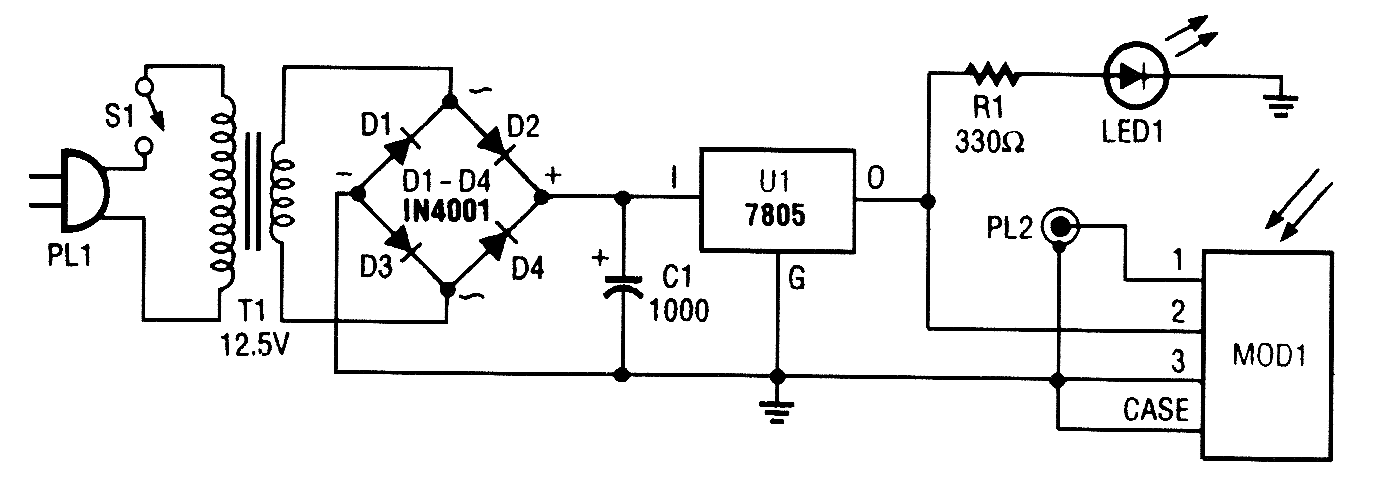
A schematic diagram for the remote analyzer is presented. The circuit operates from a basic 5-V power supply, which includes components PL1, S1, T1, a bridge rectifier made up of diodes D1 through D4, capacitor C1, and a common 5-V...

Inexpensive Remote Watering System
This remotely controlled watering system is cost-effective and easily expandable. It operates in conjunction with a conventional watering timer, enabling remote switching between nine zones. The prototype is designed for use with a bore system, where a deep-well pump must...
control electric appliances
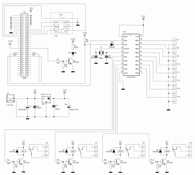
This circuit can power on or off various electric and electronic devices such as ADSL modems, personal computers, water boilers, water pumps, garage doors, lights, and more. Additionally, it allows for monitoring the status of eight switches, which can be...
Remote Control Mains Switch
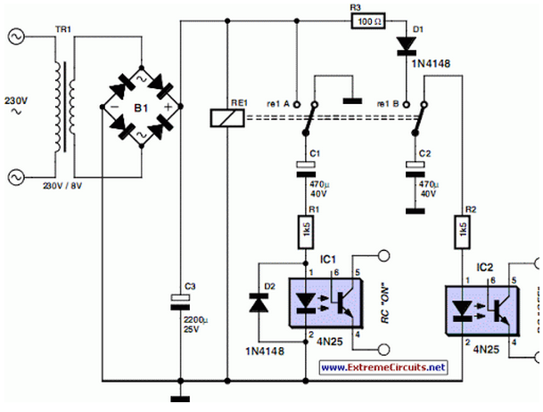
Remote Control Mains Switch
The remote control mains switch is a device designed to control the power supply to electrical appliances from a distance, typically utilizing a wireless remote control. This switch can be integrated into various applications where remote operation...