


trying to improve on the spi bus
#SPI bus
#I2C bus
#serial communication
#data transfer
#chip addressing
#protocol improvement
#embedded systems
#microcontroller
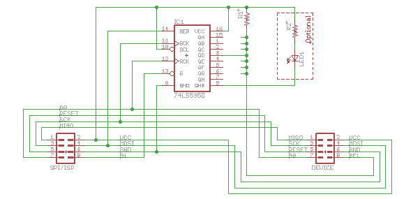
Description: Overcome a major drawback of the SPI bus. The I2C bus is a highly convenient design that requires only four wires to connect multiple chips. Each chip receives the same information but responds only to a specific address located at the beginning of each I2C message. With a single chip, there is no issue: one slave select (SS), a serial clock (SCLK), a master-out slave-in (MOSI) pin for outgoing data, and a master-in slave-out (MISO) pin for incoming data. However, complications arise when multiple chips, or slaves, are involved. While SCLK, MOSI, and MISO pins can be shared, each slave requires a separate slave select pin, which prevents the use of a true bus configuration. To address this limitation, the proposal involves utilizing all SPI signals along with power and two chip select lines, similar to the SPI/ISP connector, using B0 and B1 as the select signals. The approach consists of first sending a byte over SPI with B0 set low, followed by the actual data transfer with B1 set low. The B0 transfer selects a specific slave, while the B1 transfer occurs solely with that slave. A 74HC595 shift register provides the necessary functionality to execute this task, utilizing the three-state enable pin to control the shift register outputs. The schematic involves placing this simple circuit on each slave board, with different outputs from the shift register jumpered for each one. In the schematic, for instance, QD (the fourth bit) is wired as the slave select.
The proposed circuit design effectively addresses the limitations of the SPI bus when connecting multiple slave devices. By implementing a 74HC595 shift register, the circuit can utilize its outputs for slave selection while maintaining the shared SCLK, MOSI, and MISO lines. The shift register's three-state enable pin allows for controlled output activation, enabling seamless communication with individual slaves.
In this configuration, the first transfer over SPI is dedicated to selecting the desired slave device. This is achieved by setting the B0 pin low, which activates the corresponding output on the shift register that is connected to the selected slave's SS pin. Following this, the actual data transfer occurs with B1 set low, ensuring that the data is sent exclusively to the chosen slave. This method simplifies the wiring and reduces the number of required pins on the master device, making it an efficient solution for systems with multiple slave devices.
The schematic for this design should clearly illustrate the connections between the master device, the shift register, and the individual slave devices. Each slave board would have its unique jumper configuration for the shift register outputs, allowing for easy customization and scalability. This design not only optimizes the use of available pins but also enhances the overall functionality of the SPI bus in multi-device applications.Overcome a major drawback of the SPI bus. But to explain this, allow me to go on a little detour first. The I2C bus is an extremely convenient design, because it only needs 4 wires to connect several chips together: Each chip sees the same information, but it works because each chip has been set up to respond only to a specific addre ss on the bus. And that address happens to be conveniently located at the start of each I2C message. With one chip, there`s no problem: one slave select (SS), a serial clock (SCLK), a master-out slave-in (MOSI) pin for outgoing data, and a master-in slave-out (MISO) for incoming data (brilliant naming no confusion!). The trouble is with multiple chips, i. e. slaves. The SCLK, MOSI, and MISO pins can be shared, but not the slave select . Each slave will need a separate pin to select it. And that makes it impossible to use it as a real bus And that`s where yesterday`s post comes in. Suppose we had all the SPI signals, as well as power, as well as two chip selects. Like, eh the SPI/ISP connector, using B0 and B1 as the two select signals how convenient! So here`s the idea: first we send a byte over SPI with B0 set low and then we send the actual data with B1 set low.
The B0 transfer is used to select one specific slave, and the B1 transfer then takes place only with that slave. The good news is that a 74HC595 shift register has all the functionality needed to perform this task, by using the three-state enable pin as a gate to turn the shift register outputs on or off.
Here`s the schematic for it all: The idea is to put this simple circuit on each slave board. On each one, a different output from the shift register gets jumpered. In the above schematic, for example, QD (the 4th bit) has been wired up as slave select.
The proposed circuit design effectively addresses the limitations of the SPI bus when connecting multiple slave devices. By implementing a 74HC595 shift register, the circuit can utilize its outputs for slave selection while maintaining the shared SCLK, MOSI, and MISO lines. The shift register's three-state enable pin allows for controlled output activation, enabling seamless communication with individual slaves.
In this configuration, the first transfer over SPI is dedicated to selecting the desired slave device. This is achieved by setting the B0 pin low, which activates the corresponding output on the shift register that is connected to the selected slave's SS pin. Following this, the actual data transfer occurs with B1 set low, ensuring that the data is sent exclusively to the chosen slave. This method simplifies the wiring and reduces the number of required pins on the master device, making it an efficient solution for systems with multiple slave devices.
The schematic for this design should clearly illustrate the connections between the master device, the shift register, and the individual slave devices. Each slave board would have its unique jumper configuration for the shift register outputs, allowing for easy customization and scalability. This design not only optimizes the use of available pins but also enhances the overall functionality of the SPI bus in multi-device applications.Overcome a major drawback of the SPI bus. But to explain this, allow me to go on a little detour first. The I2C bus is an extremely convenient design, because it only needs 4 wires to connect several chips together: Each chip sees the same information, but it works because each chip has been set up to respond only to a specific addre ss on the bus. And that address happens to be conveniently located at the start of each I2C message. With one chip, there`s no problem: one slave select (SS), a serial clock (SCLK), a master-out slave-in (MOSI) pin for outgoing data, and a master-in slave-out (MISO) for incoming data (brilliant naming no confusion!). The trouble is with multiple chips, i. e. slaves. The SCLK, MOSI, and MISO pins can be shared, but not the slave select . Each slave will need a separate pin to select it. And that makes it impossible to use it as a real bus And that`s where yesterday`s post comes in. Suppose we had all the SPI signals, as well as power, as well as two chip selects. Like, eh the SPI/ISP connector, using B0 and B1 as the two select signals how convenient! So here`s the idea: first we send a byte over SPI with B0 set low and then we send the actual data with B1 set low.
The B0 transfer is used to select one specific slave, and the B1 transfer then takes place only with that slave. The good news is that a 74HC595 shift register has all the functionality needed to perform this task, by using the three-state enable pin as a gate to turn the shift register outputs on or off.
Here`s the schematic for it all: The idea is to put this simple circuit on each slave board. On each one, a different output from the shift register gets jumpered. In the above schematic, for example, QD (the 4th bit) has been wired up as slave select.

DIAL ALARM-1
This is the lowest cost dialing alarm on the market and shows what can be done with an 8-pin microcontroller. The complete circuit is shown below. You cannot see all the features of this project by looking at the circuit...

Microcontroller Clapper Switch
For those who prefer convenience, it is possible to turn the bedroom light on or off without leaving the bed simply by clapping hands. This concept inspired the design of a clap-activated light control system. Various clap switch projects can...

Cipher scheme of the module of infrared remote-control between two parties of intellectual family
This system is a control system based on a single-chip computer that allows for remote operation of lighting. The scheme primarily addresses the transmission and reception of signals, as well as program manipulation of various signals once they are processed...

Metal detector circuit
The project demonstration has been successfully completed, with the only remaining task being the final project report due on June 15, which will be integrated with a conference paper. This update marks the last entry in the electronic notebook, although...

Microcontroller based College Automation System
This project is a microcontroller-based college automation system aimed at addressing the challenges faced in educational institutions. It replaces the conventional notice board with an automated device that allows users to both hear and read the information being announced through...

Night Light Saver
A Microchip PIC12C508 8-pin CMOS microcontroller controls a night light, turning it on and off at preset times every day. It is designed to save energy, produce no electromagnetic interference (EMI), and operate without batteries, featuring a built-in lamp fixture...

Jet
The microcontroller is able to make about 7000 complete line-following decisions per second, which is almost 7 decisions per millimeter when the robot is going full speed. By upping the clock, unrolling loops, and removing my wireless debugging and extraneous...

serial communication introduction
Serial communication using UART or USART of a microcontroller 8051 AVR PIC, software implementation of half-duplex UART and MAX232 interfacing with microcontrollers 8051 AVR PIC.
The described system focuses on implementing serial communication via UART (Universal Asynchronous Receiver-Transmitter) or USART (Universal...

Protecting Microcontroller Input Pins from Soft Power Switch
A soft power switch for a microcontroller is designed such that a momentary switch can activate the circuit, including the microcontroller. When the switch is pressed a second time, the microcontroller is capable of shutting itself down after executing necessary...