


Video IsolatorCircuit
#video isolator
#audio-visual
#TV
#DVD
#signal isolation
#home entertainment
#AV devices
#video signal
#noise reduction
#interference prevention
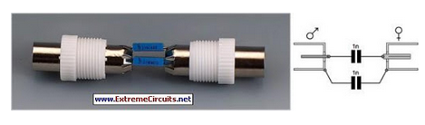
Description: Nowadays, an increasing number of audio-visual devices in homes are interconnected. This is particularly true for televisions, which may be linked to DVD players.
In modern home entertainment systems, the integration of various audio-visual devices enhances user experience and convenience. A typical setup may include a television, DVD player, gaming console, streaming device, and sound system, all interconnected to provide seamless access to multimedia content.
The connection methods can vary, including HDMI, optical audio, component video, and composite video cables. HDMI (High Definition Multimedia Interface) is the most common due to its ability to transmit both high-definition video and audio signals through a single cable, simplifying connections and reducing clutter.
In a typical schematic for such a system, the television serves as the central hub, with multiple input ports for various devices. The DVD player connects via HDMI, allowing for high-quality video playback. If additional devices such as a gaming console are included, they can also connect through HDMI or other appropriate interfaces, depending on the available ports and desired functionality.
Audio output can be routed to an external sound system, which may utilize an optical audio connection or HDMI ARC (Audio Return Channel) to ensure high-fidelity sound. This setup allows users to enjoy enhanced audio quality, particularly important for cinematic experiences.
Furthermore, smart TVs may include built-in wireless connectivity, enabling them to connect to the internet and stream content from various online platforms. This capability enhances the versatility of the system, allowing users to access a wider range of media without the need for additional hardware.
Overall, a well-designed audio-visual system can significantly improve the home entertainment experience, providing flexibility, high-quality audio and video, and ease of use through interconnected devices.These days many more audio-visual devices in the home are connected together. This is especially the case with the TV, which may be connected to a DVD pla..
In modern home entertainment systems, the integration of various audio-visual devices enhances user experience and convenience. A typical setup may include a television, DVD player, gaming console, streaming device, and sound system, all interconnected to provide seamless access to multimedia content.
The connection methods can vary, including HDMI, optical audio, component video, and composite video cables. HDMI (High Definition Multimedia Interface) is the most common due to its ability to transmit both high-definition video and audio signals through a single cable, simplifying connections and reducing clutter.
In a typical schematic for such a system, the television serves as the central hub, with multiple input ports for various devices. The DVD player connects via HDMI, allowing for high-quality video playback. If additional devices such as a gaming console are included, they can also connect through HDMI or other appropriate interfaces, depending on the available ports and desired functionality.
Audio output can be routed to an external sound system, which may utilize an optical audio connection or HDMI ARC (Audio Return Channel) to ensure high-fidelity sound. This setup allows users to enjoy enhanced audio quality, particularly important for cinematic experiences.
Furthermore, smart TVs may include built-in wireless connectivity, enabling them to connect to the internet and stream content from various online platforms. This capability enhances the versatility of the system, allowing users to access a wider range of media without the need for additional hardware.
Overall, a well-designed audio-visual system can significantly improve the home entertainment experience, providing flexibility, high-quality audio and video, and ease of use through interconnected devices.These days many more audio-visual devices in the home are connected together. This is especially the case with the TV, which may be connected to a DVD pla..

Adding sync pulses to the video signal
This section provides details for generating a composite video output signal from a camera to drive an external monitor. The circuit, designed by Peter Smith, integrates a DC-restorer, a switchable gamma corrector, and a video/sync mixer using a photodiode and...

Video Signal Carrier Circuit
In the video system shown in Figs. A and R, a single coaxial cable transmits power to a remote location, selects one of eight video channels, and returns the chosen signal. This system can select from multiple remote surveillance camera...
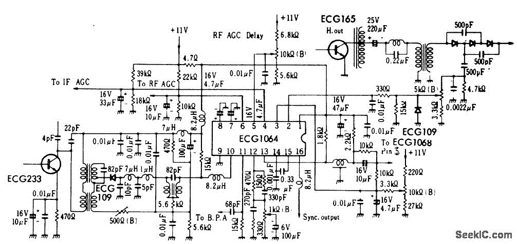
TV_video_signal_processor_circuit_1
TV video signal processor circuit. The ECG1064 chip includes a primary video amplifier, two sync pulse amplifiers, a look-out protector, a noise detector, two noise gates, an automatic gain control (AGC) detector, an intermediate frequency (IF) AGC amplifier, a base...

Video-Out Coupling
To connect a video signal to multiple destinations, a distribution amplifier is required to match the 75-ohm video cable. This amplifier terminates the incoming cable at 75 ohms and provides several outputs, each maintaining a 75-ohm output impedance. Typically, this...

Stereo Noise Reduction Circuit
The noise reduction circuit is designed to minimize disturbances that occur during pauses in music playback. It functions by attenuating the signal output during these intervals.
The noise reduction circuit operates on the principle of detecting silence or low audio signals,...

Tv Line Pulse Extractor
This circuit utilizes a sync-generator chip, a counter, and a decoder to detect the horizontal sync pulse that occurs at the beginning of line 10 in field 1 of an NTSC television picture. This circuit can be employed to compare...

Video Fader Circuit
Fading a video signal cannot be achieved merely by attenuating the composite signal, as the synchronization signal may fall below an unacceptable level.
Fading a video signal involves a careful adjustment of both the luminance and chrominance components while maintaining...

Color-tv-crosshatch-generator
This circuit serves as a simple, low-cost crosshatch generator for convergence and geometry adjustments in color televisions. It is driven by two clock signals, one for horizontal drive (IC1ab) and another for vertical drive (IC2ab). The outputs from these clocks...

ISO100 sensing signal isolation amplifier
A bridge sensor output signal precision differential instrumentation amplifier with adjustable gain IC1 amplified signal IS0100. The gain of IC1 is determined by the external resistor Rc. The IC2 current source output is sent to drive the bridge sensor, while...