


Walky-talky

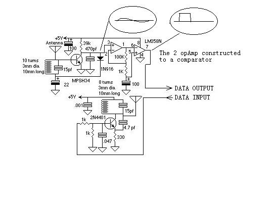
Description: The walkie-talkie presented on this website is the world's first verified project created without the use of any coils, with a communication range of up to 500 meters. The circuit diagram of the walkie-talkie is provided along with a description of its functionality.
The walkie-talkie circuit operates on the principles of radio frequency communication, utilizing a combination of transistors, resistors, capacitors, and integrated circuits to facilitate two-way communication. The absence of coils in the design suggests the use of alternative methods for signal modulation and transmission, which may include the use of high-frequency oscillators or other innovative techniques.
The circuit typically consists of a transmitter and a receiver unit. The transmitter converts audio signals into radio frequency (RF) signals, which are then transmitted through an antenna. The receiver unit captures these RF signals and demodulates them back into audio signals, allowing for real-time communication.
Key components of the circuit may include:
1. **Transistors**: Used for amplification and switching, essential for both the transmitter and receiver sections.
2. **Microcontroller**: May be employed to manage signal processing and control functions, enhancing the overall efficiency of the device.
3. **Power Supply**: A battery or rechargeable power source is required to ensure portability and operation of the device.
4. **Antenna**: A critical component for both transmitting and receiving signals over the specified range.
The design's verification indicates thorough testing and validation of its performance, ensuring reliability in communication over distances up to 500 meters. This innovation in walkie-talkie technology represents a significant advancement in the field of wireless communication, potentially offering a more compact and efficient solution compared to traditional coil-based designs.Walky-talky in this website is world first verified project made without using any coil range up to 500M circuit diagram of walky-talky with description walky-talky is communication .
The walkie-talkie circuit operates on the principles of radio frequency communication, utilizing a combination of transistors, resistors, capacitors, and integrated circuits to facilitate two-way communication. The absence of coils in the design suggests the use of alternative methods for signal modulation and transmission, which may include the use of high-frequency oscillators or other innovative techniques.
The circuit typically consists of a transmitter and a receiver unit. The transmitter converts audio signals into radio frequency (RF) signals, which are then transmitted through an antenna. The receiver unit captures these RF signals and demodulates them back into audio signals, allowing for real-time communication.
Key components of the circuit may include:
1. **Transistors**: Used for amplification and switching, essential for both the transmitter and receiver sections.
2. **Microcontroller**: May be employed to manage signal processing and control functions, enhancing the overall efficiency of the device.
3. **Power Supply**: A battery or rechargeable power source is required to ensure portability and operation of the device.
4. **Antenna**: A critical component for both transmitting and receiving signals over the specified range.
The design's verification indicates thorough testing and validation of its performance, ensuring reliability in communication over distances up to 500 meters. This innovation in walkie-talkie technology represents a significant advancement in the field of wireless communication, potentially offering a more compact and efficient solution compared to traditional coil-based designs.Walky-talky in this website is world first verified project made without using any coil range up to 500M circuit diagram of walky-talky with description walky-talky is communication .

RF oscillator uses current-feedback op amp
A current-feedback amplifier is a well-known component with many uses. Its basic block diagram shows that its input stage is a voltage follower in practice, a symmetrical emitter follower. The configuration samples the output current, converts it to voltage across...
RF communication use a sample circuit(example in AVR)
Even including labor, the actual cost of purchasing, stocking, assembly, assembly errors, more expensive PCBs (with additional holes and larger sizes), and the increased difficulty in tuning would likely result in significantly higher expenses.
The analysis of costs associated with electronic...
RF Remote control
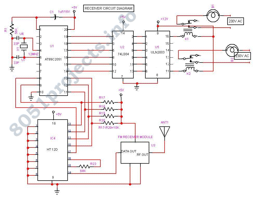
The Project Long Range Remote Control can be used to remotely control a number of Electrical or Electronic Gadgets connected to it. Unlike Infra Red remote control, this Project employs FM transmission and Reception, and hence it can be used...

RF OSCILLATOR CIRCUITS
A widely recognized circuit is the Hartley oscillator, which is characterized by a tapped coil within the LC tank circuit. The tap point of the coil is grounded. The oscillator's amplifier section functions as a common-emitter amplifier, resulting in the...

Single injector-tracer
In the "Trace" mode, the non-linear operation of the amplifier will detect modulated RF signals, which will be filtered by the 0.001 µF capacitor and heard in the headphones. In the "Inject" mode, this circuit will provide a nominal square...

rf remote control encoder and decoder
This document explains two RF 433kHz remote control chips specifically designed for remote control applications. The IC TWS-434, along with its encoder chip HT-12E from Holtek, forms a high-quality transmitter circuit, while the chip RWS-434, paired with the decoder IC...

wireless digital code lock with a status display
Warning: Missing argument 2 for wpdb::prepare(), called in /home3/nithish/public_html/btechzone.com/wp-content/plugins/sharebar/sharebar.php on line 112 and defined in /home3/nithish/public_html/btechzone.com/wp-includes/wp-db.php on line 992 Warning: Missing argument 2 for wpdb::prepare(), called in /home3/nithish/public_html/btechzone.com/wp-content/plugins/sharebar/sharebar.php on line 124 and defined in /home3/nithish/public_html/btechzone.com/wp-includes/wp-db.php on line 992 This project...
radio station blocker circuit
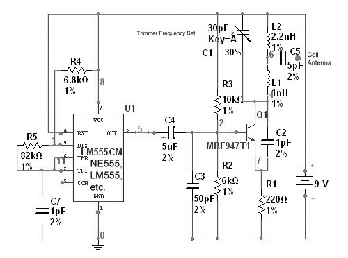
This device functions as a reversal of a radio station, sending a null signal to a selected frequency to eliminate the actual broadcast. The radio transmitter operates at a loss of 10,000W; therefore, this circuit is intended for use only...

Wide Dynamic Range Field Strength Meter
A field strength meter is a useful tool for locating a transmitter. However, a sensitive field strength meter has limitations: it responds to nearly any RF signal entering its input. This characteristic reduces the effective sensitivity of the field strength...