


Interface Circuits
#Amiga A1200
#PC AT/ATX
#power supply
#tower case
#interface circuits
#retro computing
#hardware hacking
#computer modding

Description: Building circuits to interface an Amiga A1200 to a PC AT/ATX power supply and tower case.
To create a reliable interface between an Amiga A1200 and a PC AT/ATX power supply and tower case, it is essential to design a circuit that effectively manages power requirements and signal compatibility. The Amiga A1200 typically operates on a 5V power supply, while AT/ATX power supplies provide multiple voltage outputs, including 3.3V, 5V, and 12V.
The circuit design should incorporate a power distribution board that connects the power supply outputs to the Amiga's power input. This board should include voltage regulators to ensure stable voltage levels are supplied to the Amiga. Additionally, decoupling capacitors must be placed near the power input of the Amiga to filter out noise and provide stable operation.
In terms of physical integration, the Amiga A1200 can be housed within a standard PC tower case. Proper mounting hardware should be used to secure the A1200 motherboard within the case, and appropriate cutouts must be made for ports and connectors. The power supply should be mounted securely, ensuring that all wiring is neatly organized to prevent interference and to facilitate airflow.
The circuit may also include a power switch that can control the power supply, allowing for easy operation of the Amiga A1200 from the front of the PC case. Additionally, LED indicators can be integrated to provide visual feedback on power status.
Overall, the project requires careful consideration of electrical specifications, physical layout, and user interface to ensure compatibility and functionality between the Amiga A1200 and the PC AT/ATX power supply and tower case.Building circuits to interface an Amiga A1200 to a PC AT/ATX power supply and tower case..
To create a reliable interface between an Amiga A1200 and a PC AT/ATX power supply and tower case, it is essential to design a circuit that effectively manages power requirements and signal compatibility. The Amiga A1200 typically operates on a 5V power supply, while AT/ATX power supplies provide multiple voltage outputs, including 3.3V, 5V, and 12V.
The circuit design should incorporate a power distribution board that connects the power supply outputs to the Amiga's power input. This board should include voltage regulators to ensure stable voltage levels are supplied to the Amiga. Additionally, decoupling capacitors must be placed near the power input of the Amiga to filter out noise and provide stable operation.
In terms of physical integration, the Amiga A1200 can be housed within a standard PC tower case. Proper mounting hardware should be used to secure the A1200 motherboard within the case, and appropriate cutouts must be made for ports and connectors. The power supply should be mounted securely, ensuring that all wiring is neatly organized to prevent interference and to facilitate airflow.
The circuit may also include a power switch that can control the power supply, allowing for easy operation of the Amiga A1200 from the front of the PC case. Additionally, LED indicators can be integrated to provide visual feedback on power status.
Overall, the project requires careful consideration of electrical specifications, physical layout, and user interface to ensure compatibility and functionality between the Amiga A1200 and the PC AT/ATX power supply and tower case.Building circuits to interface an Amiga A1200 to a PC AT/ATX power supply and tower case..

Battery charger or Power Supply 14 volt 4 ampere
The schematic diagram originates from a circuit designed as a battery charger/power supply with an output of 14V and a maximum current of 4A, utilizing the VN64GA MOSFET. This high-performance battery charger is specifically engineered for gelled electrolyte lead-acid batteries,...

Evaluation Board For The Ad9834 Direct Digital Synthesizer
This document outlines the design of a low-cost 90 W flyback switching power supply intended for use in a multi-sync color monitor. To reduce screen interference caused by switching noise, the power supply can be automatically synchronized to the fixed...

Switching Regulator Circuit
This example presents a switch DC regulated power supply circuit designed for buck-mode +5V applications. It consists of a power supply circuit, an impulsator, a voltage sampling or pulse width modulation circuit, and a buffering driver circuit, as illustrated in...

Step-up switching power supply circuit diagram
The design of the power supply circuit diagram utilizes an oscillator circuit from the 74HC series of CMOS logic circuits, with a MOSFET as the switching device. This configuration allows for the development of small-scale power supplies suitable for portable...

Output sampling winding isolated switching power supply
The diagram illustrates the output sampling winding of an isolated switching power supply. In the diagram, T represents a high-frequency transformer; N2 denotes the self-oscillation positive feedback winding; N3 is the error amplifier; VTS is the winding that provides the...
Circuit diagrams and Schematic
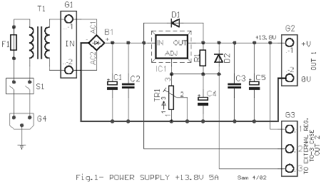
This AC to DC power supply can output 5A in continuous operation and 12A peak current. This type of DC power supply uses a PCB, allowing for two case types for IC1: TO-220 or TO-3. The regulation of this 12-volt...

A 12 Volt Switching Power Supply
This circuit is designed for individuals needing to boost or drop a voltage. The output operates at high frequency but can be rectified and filtered to provide a DC output. When rectifying high frequencies, it is essential to utilize high-speed...

FSP107-2PS01 two-in-one power panel circuit analysis
The main component is the LG26 one-inch screens integrated with the FSP107-2PS01 two-in-one electrical power package, which utilizes a direct drive CCFL modulator tube. This setup is compatible with screens from other manufacturers, such as Samsung and AU, but requires...

Alarm Power Supply
This Power Supply is suitable for the Modular Burglar Alarm. However, it has other applications. It is designed to provide an output of 12-volts, with a current of up to 1-amp. In the event of mains failure, the back-up battery...