


pic dmx interface software
#DMX
#PIC microcontroller
#lighting control
#theatre equipment
#interface software
#microcontroller
#lighting board
#Strand
#home automation
#control systems

Description: The project concept originated nearly two years ago during research for a new lighting board for a small theater. The existing board was nearly twenty years old and in dire need of replacement. However, the costs associated with purchasing new equipment from manufacturers like Strand were prohibitively high, leading to the abandonment of that idea. During this period, interest shifted towards computer-based lighting consoles, which some DIY enthusiasts had assembled and shared limited information about online, such as the product from ENTTEC. Various systems exist that utilize a serial interface to connect to a computer, where signal-level data from a parallel port, serial port, or USB is converted into RS-485 signal-level data by a chip and transmitted to the dimmer. Essentially, the computer broadcasts a DMX signal, which is then slightly amplified and sent to the dimmer. This prompted the decision to create a custom DMX interface based on existing DMX Dongle schematics. A significant issue was identified with these systems: the DMX specification mandates continuous refreshing of light data to the dimmers at approximately 44Hz. This necessitates sending a full 512-channel packet from the computer to the dimmer 44 times per second. A gap longer than half a second in this stream could result in light flicker, which is unacceptable during performances. Many of these systems relied on the computer to broadcast the DMX packet, so any computer freeze—even for half a second—would interrupt the transmission flow. Consequently, a unique DMX interface was developed from scratch, inspired by several similar projects. Over four months, a serial port interface was created that, using a serial UART interface and a memory buffer, required minimal processor power to function and could continuously broadcast channel data even with the computer powered off. The components for this device are estimated to cost around $40 from an electrical supply store, and it is capable of controlling up to 244 channels with a refresh rate of up to 80Hz. The initial hardware design was based on the previously mentioned DMX Dongle, but a PIC16F628 chip was chosen over the PIC16F84 due to its lack of requirement for an external oscillator, simplifying construction. A programmer board was also necessary to upload the assembler files onto the chip. After a week of trial and error, ICPRog software and the JDM Programmer were selected for this purpose. All schematics and resources for the programmer and DMX interface are available for download in a ZIP file. The interface began with just the PIC, revealing the need for an RS485 transceiver to enable communication with the dimmer. The PIC outputs signal data where a '1' corresponds to +5V (High) and a '0' corresponds to +0V (Low). The RS485 transceiver takes this signal and outputs it on two pins, which are connected to the dimmer. When pin 1 is at +7V and pin 2 is at -7V, this represents an electrical High. Conversely, when pin 1 is at -7V and pin 2 is at +7V, it signifies an electrical Low. This standard was established for DMX communication to ensure that any electrostatic disturbances in the line affect both signal parts equally, thus minimizing data distortion. With this setup, and after extensive code adjustments, a high signal was successfully sent from the computer to the chip, leading to all DMX channels being set to full.
The electronic schematic for the DMX interface includes several critical components. The core of the system is the PIC16F628 microcontroller, which processes the DMX data and manages the communication protocol. The microcontroller is connected to an RS485 transceiver, such as the MAX485, which facilitates the conversion of TTL logic levels from the PIC to the differential signaling required for DMX communication. The RS485 transceiver is connected to the dimmer through twisted pair cabling, ensuring minimal interference and signal degradation over longer distances.
Power supply considerations are also crucial; the microcontroller and RS485 transceiver typically operate at +5V, which can be supplied via a voltage regulator if a higher voltage source is used. Proper decoupling capacitors should be placed close to the power pins of both the PIC and the transceiver to filter out noise and ensure stable operation.
The programming of the PIC microcontroller is achieved through a dedicated programming interface, which can be implemented using a JDM programmer. The programming connections include MCLR, VDD, VSS, and the data lines for the programming signal. The firmware loaded onto the PIC includes routines to handle DMX packet generation, manage the timing necessary for the 44Hz refresh rate, and implement error-checking mechanisms to ensure data integrity.
In summary, this DMX interface project combines hardware design, microcontroller programming, and communication protocol implementation to create a robust solution for controlling stage lighting. The ability to continuously broadcast DMX data without relying on the computer's uptime significantly enhances the reliability of lighting control in performance environments.The idea for the project started nearly two years ago, while I was researching the purchase of a new lighting board for a small theatre where I was working at the time. While our old board was nearly twenty years old, and desperately in need of a replacement, the costs of purchasing any new equipment from Strand, or other brand name providers, end
ed up being so prohibitively high that we were forced to abandon the idea of new equipment entirely. Around this time I began looking into computer-based lighting consoles, which a few DIY-ers had pieced together, and posted some limited information on the internet. See this product from ENTTEC. There are several more systems, too, all essentially based on a serial interface to the computer, in which signal-level data from either the parallel port, serial port, or USB is converted into RS-485-signal-level data by a chip, and sent down the line to the dimmer.
Essentially the computer broadcasts a DMX signal, which then gets a slight voltage boost, and sent down to the dimmer. I set out, around that time, to build my own system based on the DMX Dongle schematics. I quickly realized a major flaw with all of these systems. The DMX specification requires the light data to be continuously refreshed to the dimmers, at about 44Hz.
This means that a full 512 channel packet it sent from the computer to the dimmer 44 times per second. A gap in this stream longer than half a second could cause a flicker of the lights, which is not an option when running lighting for any type of performance.
However, most of these systems were using the computer to broadcast the DMX packet, meaning that if, for whatever reason, the computer should freeze up for even half a second, the flow of transmission would be interrupted. For this reason, I decided to create my own DMX interface from scratch, based on the work of several similar projects.
Over the course of four months, I was able to develop a serial port interface which, through use of a serial UART interface and a memory buffer, requires minimal processor power to operate, and will continuously broadcast channel data, even if the computer is powered off. This article will explain every step in the design and construction. The parts for this device will cost about $40 from an elecrical supply store, and when finished, it can control up to 244 channels, with a refresh rate of up to 80Hz.
I based the initial hardware design off of the DMX Dongle, mentioned earlier, but opted to use a PIC16f628 chip instead of the PIC16f84. It is essentialy the same chip, but doesn`t require an external oscillator, which makes building it a little bit easier.
I also needed a programmer board to write the assembler files onto the chip. After a week of trial and error, I eventually settled on ICPRog for the software, and the JDM Programmer (schematic to the left). All of the schematics and resources for the programmer and dmx interface can be downloaded together in a ZIP file, below.
The interface began with just the PIC, where it became quickly apparent that an RS485 transciever would be necessary to facilitate communication with the dimmer. In essence, the PIC is going to output signal data with a 1 ³ equalling a +5v High , and a 0 ³ equalling a +0v Low .
The RS485 transciever inputs that signal and outputs it on two pins, which we send to the dimmer. When pin 1 is at +7v and pin 2 is at -7v, it equals an electrical High . When pin 1 is at -7v, and pin 2 is at +7v, it equals an elecrical Low . This was the standard decided on for DMX communication, as any electrostatic disturbances in the line will affect both parts of the signal equally, and thus eliminate the possibility of data distortion. With this in place, and after much tinkering with the code (see below), we were able to send a high signal from the computer to the chip, which then caused the chip to set all DMX channels to full.
The next step was to b
The electronic schematic for the DMX interface includes several critical components. The core of the system is the PIC16F628 microcontroller, which processes the DMX data and manages the communication protocol. The microcontroller is connected to an RS485 transceiver, such as the MAX485, which facilitates the conversion of TTL logic levels from the PIC to the differential signaling required for DMX communication. The RS485 transceiver is connected to the dimmer through twisted pair cabling, ensuring minimal interference and signal degradation over longer distances.
Power supply considerations are also crucial; the microcontroller and RS485 transceiver typically operate at +5V, which can be supplied via a voltage regulator if a higher voltage source is used. Proper decoupling capacitors should be placed close to the power pins of both the PIC and the transceiver to filter out noise and ensure stable operation.
The programming of the PIC microcontroller is achieved through a dedicated programming interface, which can be implemented using a JDM programmer. The programming connections include MCLR, VDD, VSS, and the data lines for the programming signal. The firmware loaded onto the PIC includes routines to handle DMX packet generation, manage the timing necessary for the 44Hz refresh rate, and implement error-checking mechanisms to ensure data integrity.
In summary, this DMX interface project combines hardware design, microcontroller programming, and communication protocol implementation to create a robust solution for controlling stage lighting. The ability to continuously broadcast DMX data without relying on the computer's uptime significantly enhances the reliability of lighting control in performance environments.The idea for the project started nearly two years ago, while I was researching the purchase of a new lighting board for a small theatre where I was working at the time. While our old board was nearly twenty years old, and desperately in need of a replacement, the costs of purchasing any new equipment from Strand, or other brand name providers, end
ed up being so prohibitively high that we were forced to abandon the idea of new equipment entirely. Around this time I began looking into computer-based lighting consoles, which a few DIY-ers had pieced together, and posted some limited information on the internet. See this product from ENTTEC. There are several more systems, too, all essentially based on a serial interface to the computer, in which signal-level data from either the parallel port, serial port, or USB is converted into RS-485-signal-level data by a chip, and sent down the line to the dimmer.
Essentially the computer broadcasts a DMX signal, which then gets a slight voltage boost, and sent down to the dimmer. I set out, around that time, to build my own system based on the DMX Dongle schematics. I quickly realized a major flaw with all of these systems. The DMX specification requires the light data to be continuously refreshed to the dimmers, at about 44Hz.
This means that a full 512 channel packet it sent from the computer to the dimmer 44 times per second. A gap in this stream longer than half a second could cause a flicker of the lights, which is not an option when running lighting for any type of performance.
However, most of these systems were using the computer to broadcast the DMX packet, meaning that if, for whatever reason, the computer should freeze up for even half a second, the flow of transmission would be interrupted. For this reason, I decided to create my own DMX interface from scratch, based on the work of several similar projects.
Over the course of four months, I was able to develop a serial port interface which, through use of a serial UART interface and a memory buffer, requires minimal processor power to operate, and will continuously broadcast channel data, even if the computer is powered off. This article will explain every step in the design and construction. The parts for this device will cost about $40 from an elecrical supply store, and when finished, it can control up to 244 channels, with a refresh rate of up to 80Hz.
I based the initial hardware design off of the DMX Dongle, mentioned earlier, but opted to use a PIC16f628 chip instead of the PIC16f84. It is essentialy the same chip, but doesn`t require an external oscillator, which makes building it a little bit easier.
I also needed a programmer board to write the assembler files onto the chip. After a week of trial and error, I eventually settled on ICPRog for the software, and the JDM Programmer (schematic to the left). All of the schematics and resources for the programmer and dmx interface can be downloaded together in a ZIP file, below.
The interface began with just the PIC, where it became quickly apparent that an RS485 transciever would be necessary to facilitate communication with the dimmer. In essence, the PIC is going to output signal data with a 1 ³ equalling a +5v High , and a 0 ³ equalling a +0v Low .
The RS485 transciever inputs that signal and outputs it on two pins, which we send to the dimmer. When pin 1 is at +7v and pin 2 is at -7v, it equals an electrical High . When pin 1 is at -7v, and pin 2 is at +7v, it equals an elecrical Low . This was the standard decided on for DMX communication, as any electrostatic disturbances in the line will affect both parts of the signal equally, and thus eliminate the possibility of data distortion. With this in place, and after much tinkering with the code (see below), we were able to send a high signal from the computer to the chip, which then caused the chip to set all DMX channels to full.
The next step was to b

pic based modified sine wave inverter
A PIC-based inverter circuit is being developed that utilizes two P-channel MOSFETs (F9540N) along with a center-tapped 12-0-12/230V transformer.
The proposed circuit design incorporates a microcontroller from the PIC family, which serves as the main control unit for the inverter operation....

Cipher scheme of the module of infrared remote-control between two parties of intellectual family
This system is a control system based on a single-chip computer that allows for remote operation of lighting. The scheme primarily addresses the transmission and reception of signals, as well as program manipulation of various signals once they are processed...
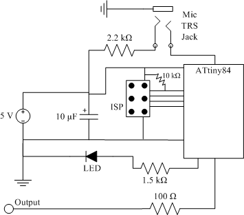
clap sensor construction
The clap sensor is a straightforward circuit that consists of a PC microphone, a microcontroller, and an output. The circuit design features the ATtiny84 microcontroller, chosen for familiarity with the AVR architecture and accessibility to necessary tools. The ATtiny84 is...
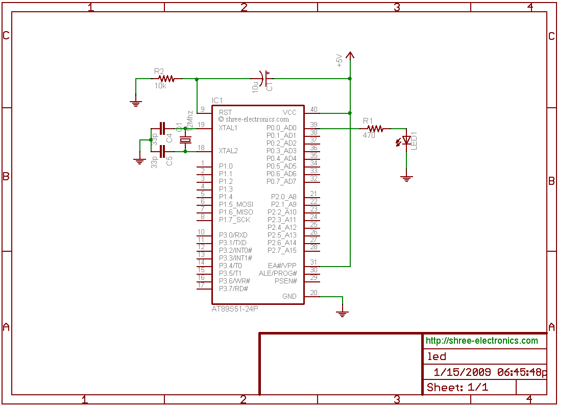
microcontroller led interfacing
The initial step often taken when learning about any microcontroller or embedded system is to make an LED blink. The circuit presented below illustrates the setup for interfacing an LED. Note: Due to the large dimensions of the circuit diagram,...

analog light dimmer circuit connected to microcontroller
Assistance is required to modify a light dimmer circuit connected to a PIC12C508 microcontroller. This circuit is designed for the...
The light dimmer circuit utilizing the PIC12C508 microcontroller serves to control the brightness of a light source through pulse width modulation...

delay circuit for photography
This article outlines the construction of a simple microcontroller-based delay circuit designed for photographic applications such as drop or high-speed photography. It can control the trigger lag of cameras and flash units, generate periodic trigger pulses, or manage magnetic valves....

servo controller
A servo controller designed to control a servo motor via a serial port using a PIC microcontroller. The project encompasses both source code details and schematic diagrams.
The servo controller operates by interfacing a PIC microcontroller with a servo motor, enabling...

Robo Atmega328p project
This project was designed to introduce a friend to microcontrollers and circuits using various functionalities and spare parts. A PS2 numpad was utilized as the key entry mechanism, which was found at a thrift store and included the necessary connector....

Night Light Saver
A Microchip PIC12C508 8-pin CMOS microcontroller controls a night light, turning it on and off at preset times every day. It is designed to save energy, produce no electromagnetic interference (EMI), and operate without batteries, featuring a built-in lamp fixture...