


quick key adapter 10 button hid keyboard using pic18f14k50
#PIC18F14K50
#HID
#USB
#keyboard
#input device
#microcontroller
#programming
#DIY electronics
#USB interface
#button inputs
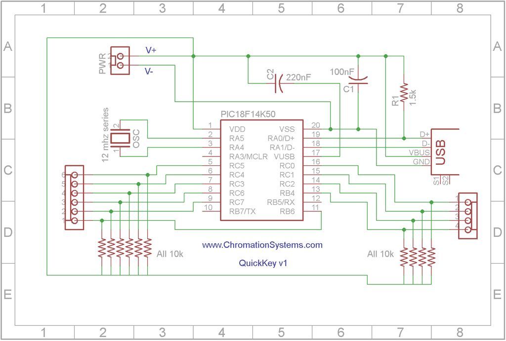
Description: Quick Key Adapter, 10 Button HID Keyboard. This document outlines the process of creating a USB-connected Human Interface Device (HID) keyboard featuring 10 button inputs.
The Quick Key Adapter is designed to facilitate user interaction through a compact keyboard interface. The project involves constructing a USB HID keyboard that allows for the integration of up to 10 distinct buttons, each capable of sending specific signals to a host device, such as a computer or microcontroller.
The core of the design utilizes a microcontroller that supports USB HID functionality. Common choices for this application include the ATmega32U4 or the Teensy series of microcontrollers, which can emulate keyboard inputs over USB. The microcontroller is programmed to recognize button presses and translate them into keyboard commands.
The circuit is typically structured as follows:
1. **Microcontroller**: Acts as the central processing unit of the keyboard. It manages the input from the buttons and communicates with the host device via USB.
2. **Button Inputs**: Each of the 10 buttons is connected to a digital input pin on the microcontroller. Pull-up resistors may be employed to ensure that the input pins read high when the buttons are not pressed.
3. **USB Connection**: A USB connector is interfaced with the microcontroller, allowing it to be powered and communicate with external devices. The microcontroller firmware must be configured to initialize the USB connection and define the HID report descriptor, which specifies how the button presses are interpreted.
4. **Power Supply**: The circuit can be powered through the USB connection, eliminating the need for an external power source. This feature enhances portability and ease of use.
5. **Firmware**: The microcontroller will require custom firmware to define the behavior of the button inputs. This includes debouncing logic to prevent multiple signals from being sent when a button is pressed and released quickly.
6. **Enclosure**: To protect the components and provide a user-friendly interface, an enclosure can be designed to house the microcontroller and buttons. This can be 3D printed or constructed from other materials.
The Quick Key Adapter serves various applications, including gaming, accessibility devices, or custom input solutions for specific software. By allowing users to program each button to perform different actions, it enhances productivity and user experience. Overall, this project exemplifies the integration of hardware and software to create a functional and customizable input device.Quick Key Adapter, 10 Button HID Keyboard This Instructable covers creating a USB connected Human Interface Device Keyboard that has 10 button inputs which..
The Quick Key Adapter is designed to facilitate user interaction through a compact keyboard interface. The project involves constructing a USB HID keyboard that allows for the integration of up to 10 distinct buttons, each capable of sending specific signals to a host device, such as a computer or microcontroller.
The core of the design utilizes a microcontroller that supports USB HID functionality. Common choices for this application include the ATmega32U4 or the Teensy series of microcontrollers, which can emulate keyboard inputs over USB. The microcontroller is programmed to recognize button presses and translate them into keyboard commands.
The circuit is typically structured as follows:
1. **Microcontroller**: Acts as the central processing unit of the keyboard. It manages the input from the buttons and communicates with the host device via USB.
2. **Button Inputs**: Each of the 10 buttons is connected to a digital input pin on the microcontroller. Pull-up resistors may be employed to ensure that the input pins read high when the buttons are not pressed.
3. **USB Connection**: A USB connector is interfaced with the microcontroller, allowing it to be powered and communicate with external devices. The microcontroller firmware must be configured to initialize the USB connection and define the HID report descriptor, which specifies how the button presses are interpreted.
4. **Power Supply**: The circuit can be powered through the USB connection, eliminating the need for an external power source. This feature enhances portability and ease of use.
5. **Firmware**: The microcontroller will require custom firmware to define the behavior of the button inputs. This includes debouncing logic to prevent multiple signals from being sent when a button is pressed and released quickly.
6. **Enclosure**: To protect the components and provide a user-friendly interface, an enclosure can be designed to house the microcontroller and buttons. This can be 3D printed or constructed from other materials.
The Quick Key Adapter serves various applications, including gaming, accessibility devices, or custom input solutions for specific software. By allowing users to program each button to perform different actions, it enhances productivity and user experience. Overall, this project exemplifies the integration of hardware and software to create a functional and customizable input device.Quick Key Adapter, 10 Button HID Keyboard This Instructable covers creating a USB connected Human Interface Device Keyboard that has 10 button inputs which..

UsbProg-SHARP
This project is a variant of the UsbProg project developed by Benedikt Sauter. The schematics, board layout, and firmware have been released as an open-source project. Modifications include the option to place a jumper across JP3 pins 2 and 3,...

HP 200LX USB / Power Supply dongle
A personal digital assistant was introduced in 1994, often referred to as a palmtop computer. It was notable for being, with minor exceptions, an MS-DOS-compatible computer in a palmtop format. It featured a monochrome graphic display, a QWERTY keyboard, a...
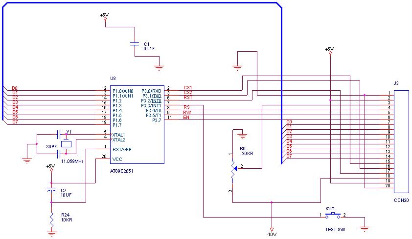
graphical LCDs with a microcontroller
How can graphical LCDs be controlled using a microcontroller? Is there any datasheet available?
Graphical LCDs (Liquid Crystal Displays) are widely used in various electronic applications for displaying complex graphics and text. To control these displays with a microcontroller, several steps...

Layout Control Mother Board
The layout control motherboard is designed to facilitate the management of various sections of a layout. It features a microcontroller that connects to the MRNet bus and multiple slots for inexpensive control and sensor boards. All control and sensor boards...

Talking Yoda head
The talking Yoda head consists of a Yoda mask and a microcontroller system to achieve the desired operation/effect. The basic operation of the project was specified as follows: The head was to be placed inside a closed box. Upon opening...

F232 is USB powered
The F232 device is powered via USB, but it requires a level translator at its output. The transmit (Tx) signal from the F232 must be converted to RS232 levels, as the receiving side has a maximum voltage requirement. The receive...

microcontroller How does this power supply circuit work? (MCU + LM317)
The filter consisting of resistors R1, R2, and capacitor C1 integrates the PWM waveform. The purpose of the operational amplifier appears to be that of a non-inverting amplifier, with the gain determined by resistors R6 and R7. However, the need...

Wiring diagram check up for usb interfaced avr
The 5 V from USB appears to be powering the LED on the laptop power brick. Therefore, even when the power brick is turned off at the wall outlet, the LED remains illuminated. When the USB is unplugged, the LED...

pc based digital ic tester
Check the following ICs: 7400, 7402, 7404, 7408, 7432, 7486. A Visual Basic program is utilized to display the results on the PC. The microcontroller AT89S52 receives the IC number from the PC, verifies the logic gates with the truth...