


spi schematics
#SPI
#Atmel AVR
#8051
#ISP
#Faraday Cup
#electron microprobes
#beam currents
#calibration
#schematic
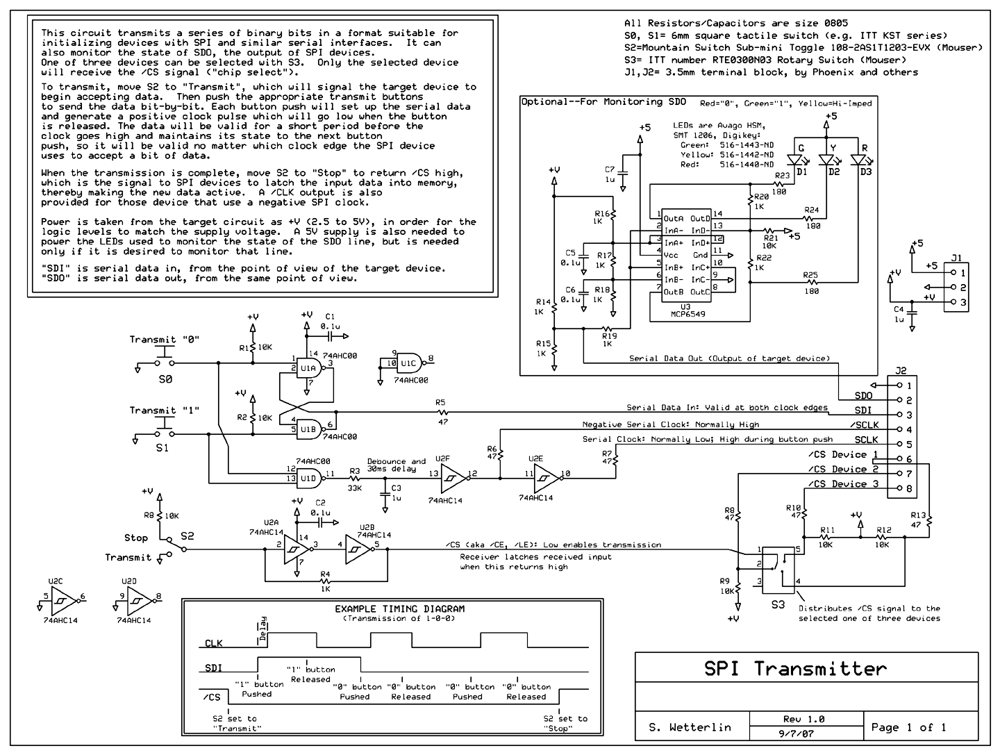
Description: Schematic for the SPI Supplies Faraday Cup. This document provides a detailed examination of the diagrams for the SPI Supplies stand-alone Faraday Cup, which is utilized for calibrating beam currents in wavelength dispersive electron microprobes, as well as interfacing with Atmel AVR and 8051 series ISP.
The schematic for the SPI Supplies Faraday Cup is designed to facilitate accurate measurements of electron beam currents, a critical parameter in electron microprobe applications. The Faraday Cup operates by capturing electrons emitted from a beam, allowing for precise current measurements that are essential for calibrating the system's performance.
The design includes several key components: a conductive cup that collects the electrons, a current amplifier to enhance the signal for measurement, and a digital interface for data logging and processing. The Faraday Cup is connected to a power supply that ensures proper operation of the current amplifier, and the output is routed to a microcontroller, which may be an Atmel AVR or a device from the 8051 series. This microcontroller processes the captured data and interfaces with other system components, allowing for real-time monitoring and adjustments based on the measured current.
The schematic should also include details on the power supply requirements, typical voltage levels, and the connections for the input and output signals. Proper grounding and shielding techniques are essential to minimize noise and ensure accurate measurements. Additionally, provisions for calibration and maintenance should be indicated to support the longevity and reliability of the device in various operational environments.
Overall, the schematic provides a comprehensive guide for assembling and utilizing the SPI Supplies Faraday Cup, ensuring that users can achieve high precision in their electron microprobe measurements.Schematic for the SPI Supplies Faraday Cup Take a detailed look at the diagrams for the SPI Supplies stand-alone Faraday Cup for calibrating beam currents in wavelength dispersive electron microprobes and . -> Atmel AVR and 8051 series ISP..
The schematic for the SPI Supplies Faraday Cup is designed to facilitate accurate measurements of electron beam currents, a critical parameter in electron microprobe applications. The Faraday Cup operates by capturing electrons emitted from a beam, allowing for precise current measurements that are essential for calibrating the system's performance.
The design includes several key components: a conductive cup that collects the electrons, a current amplifier to enhance the signal for measurement, and a digital interface for data logging and processing. The Faraday Cup is connected to a power supply that ensures proper operation of the current amplifier, and the output is routed to a microcontroller, which may be an Atmel AVR or a device from the 8051 series. This microcontroller processes the captured data and interfaces with other system components, allowing for real-time monitoring and adjustments based on the measured current.
The schematic should also include details on the power supply requirements, typical voltage levels, and the connections for the input and output signals. Proper grounding and shielding techniques are essential to minimize noise and ensure accurate measurements. Additionally, provisions for calibration and maintenance should be indicated to support the longevity and reliability of the device in various operational environments.
Overall, the schematic provides a comprehensive guide for assembling and utilizing the SPI Supplies Faraday Cup, ensuring that users can achieve high precision in their electron microprobe measurements.Schematic for the SPI Supplies Faraday Cup Take a detailed look at the diagrams for the SPI Supplies stand-alone Faraday Cup for calibrating beam currents in wavelength dispersive electron microprobes and . -> Atmel AVR and 8051 series ISP..

8051 Selling Leads
This circuit features a DS1236 component that monitors and controls the power supply and software execution of a processor-based system, while also providing a pushbutton reset function. An out-of-tolerance condition triggers the RST and RST outputs to enter the active...

SPI-Flash Programmer 3.7
This SPI Flash Programmer can be utilized for both in-system programming and as a standalone serial flash programmer for Atmel SPI programmable devices. The hardware interface of the programmer is managed through the PC's parallel port, with control signals from...

interface 16x2 lcd with 8051 microcontroller at89c51
INTRODUCTION It is essential to monitor the operation of nearly all automated and semi-automated devices, such as washing machines and autonomous systems.
Monitoring the functionality of automated and semi-automated devices is crucial for ensuring optimal performance and reliability. This can be...

ISP microcontroller PLC implement method
A slice of the SM2965 includes a canonical 80C32 microcontroller, FLASH memory, E2PROM (28SF512), SRAM for static data storage, and a watchdog timer (WDT). The cost performance of the SM2965 is notably high. This device is designed as a single-piece...
Controlling of Stepper Motor rotation in both direction using 8051 Microcontroller
Stepper motors consist of a permanent magnet rotating shaft, known as the rotor, and electromagnets on the stationary part that surrounds the motor, referred to as the stator. One complete rotation of a stepper motor is illustrated. At position 1,...

Circuit & Code for Typing Assistant using 8051 microcontroller & PS/2 port of Computer
Project with Circuit and Code for a Typing Assistant using the 8051 microcontroller (AT89S52) and the PS/2 keyboard port of a computer. The project also explains the interfacing of the PS/2 port of a computer with the 8051 microcontroller.
The Typing...

ultrasonic sensor interfacing with 8051
To enable a robot to detect objects in its surroundings, an ultrasonic sensor is recommended. While infrared (IR) sensors are inexpensive, their operational range can fluctuate due to ambient light changes, resulting in inaccurate range measurements. Ultrasonic sensors operate based...

In System Programming (ISP) for ATMEL chips
In-System Programming (ISP) allows for the serial programming of a microcontroller while it remains on the board, eliminating the need to remove the chip. This method provides a straightforward and cost-effective solution for programming and debugging microcontroller-based projects, whether for...

ROM and RAM Emulator for 8051
If the green LED is illuminated, the slave microcontroller unit (MCU) is activated. The MAX690 component preserves the memory contents during power-off conditions. No resources from the slave MCU are utilized. When employing a SAB-C515, it is possible to develop...