


2 Input Pulses Frequency Comparator
#frequency comparator
#74HCT74
#74HCT00
#LM311
#D-type flip-flops
#NAND gate
#pulse trains
#digital logic

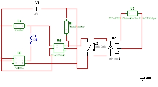
Description: This circuit uses a 74HCT74, 74HCT00, and a LM311 to form a frequency comparator. The two pulse trains are fed to two D-type flip-flops (triggered by the leading edges). The flip-flops' outputs are compared in a NAND gate. If the output of the NAND gate becomes "0", the flip-flops are reset. If the frequency of F1 is higher than the frequency of F2, the signal "Q2" consists of needles and "Q1" is a pulse train. More: Therefore, the energy content of Q1 is higher than that of Q2. Q1 and Q2 come via a low-pass filter (consisting of R1, R2 and C1) and are compared by an analog comparator circuit (IC3). The comparator drives an LED and can act as a digital output.
The described circuit implements a frequency comparator using a combination of digital and analog components to evaluate and compare the frequencies of two input signals. The core of the system is formed by two D-type flip-flops (74HCT74), which are configured to capture the leading edges of the incoming pulse trains, F1 and F2. The outputs of these flip-flops, denoted as Q1 and Q2, are then fed into a NAND gate (74HCT00). The NAND gate serves as a logic element that resets the flip-flops when its output is low, indicating that the frequencies of the two signals are equal or that F2 has a higher frequency than F1.
In the operation of the circuit, if F1 has a higher frequency than F2, Q1 will produce a continuous pulse train while Q2 will exhibit a needle-like output. This behavior indicates that the energy content of Q1 is greater than that of Q2, which can be utilized for further processing or signaling.
To ensure that the signals are clean and free from high-frequency noise, Q1 and Q2 are passed through a low-pass filter, which is composed of resistors R1, R2 and capacitor C1. This filtering stage smooths the pulse trains, allowing for a more accurate comparison of their average levels.
The filtered signals are subsequently fed into an analog comparator circuit (LM311), which compares the amplitudes of Q1 and Q2. The output of the LM311 can drive an LED, providing a visual indication of the comparison result. Additionally, this output can be utilized as a digital signal, allowing for integration with other digital logic circuits or microcontrollers for further processing or control applications.
This frequency comparator circuit is valuable in various applications such as frequency measurement, signal integrity testing, and in systems where frequency monitoring is critical for performance optimization.This circuit uses a 74HCT74, 74HCT00, and a LM311 to form a frequency comparator. The two pulse trains are fed to two D-type flip-flops (triggered by the leading edges). The flip-flops' outputs are compared in a NAND gate. If the output of the NAND gate becomes "0", the flip-flops are reset. If the frequency of F1 is higher than the frequency of F2, the signal "Q2" consists of needles and "Q1" is a pulse train. Therefore, the energy content of Q1 is higher than that of Q2. Q1 and Q2 come via a low-pass filter (consisting of R1, R2 and C1) and are compared by an analog comparator circuit (IC3). The comparator drives an LED and can act as a digital output. For the
The described circuit implements a frequency comparator using a combination of digital and analog components to evaluate and compare the frequencies of two input signals. The core of the system is formed by two D-type flip-flops (74HCT74), which are configured to capture the leading edges of the incoming pulse trains, F1 and F2. The outputs of these flip-flops, denoted as Q1 and Q2, are then fed into a NAND gate (74HCT00). The NAND gate serves as a logic element that resets the flip-flops when its output is low, indicating that the frequencies of the two signals are equal or that F2 has a higher frequency than F1.
In the operation of the circuit, if F1 has a higher frequency than F2, Q1 will produce a continuous pulse train while Q2 will exhibit a needle-like output. This behavior indicates that the energy content of Q1 is greater than that of Q2, which can be utilized for further processing or signaling.
To ensure that the signals are clean and free from high-frequency noise, Q1 and Q2 are passed through a low-pass filter, which is composed of resistors R1, R2 and capacitor C1. This filtering stage smooths the pulse trains, allowing for a more accurate comparison of their average levels.
The filtered signals are subsequently fed into an analog comparator circuit (LM311), which compares the amplitudes of Q1 and Q2. The output of the LM311 can drive an LED, providing a visual indication of the comparison result. Additionally, this output can be utilized as a digital signal, allowing for integration with other digital logic circuits or microcontrollers for further processing or control applications.
This frequency comparator circuit is valuable in various applications such as frequency measurement, signal integrity testing, and in systems where frequency monitoring is critical for performance optimization.This circuit uses a 74HCT74, 74HCT00, and a LM311 to form a frequency comparator. The two pulse trains are fed to two D-type flip-flops (triggered by the leading edges). The flip-flops' outputs are compared in a NAND gate. If the output of the NAND gate becomes "0", the flip-flops are reset. If the frequency of F1 is higher than the frequency of F2, the signal "Q2" consists of needles and "Q1" is a pulse train. Therefore, the energy content of Q1 is higher than that of Q2. Q1 and Q2 come via a low-pass filter (consisting of R1, R2 and C1) and are compared by an analog comparator circuit (IC3). The comparator drives an LED and can act as a digital output. For the

It uses NAND gate transistor and humidity control circuit
Two NAND gates (Di, Dz) and a resistor (Rz) along with capacitors (C1, etc.) form an RC self-excited multivibrator with an oscillation frequency of 2.5 Hz and an oscillation amplitude of 4 V. This circuit is used as a probe...

frequency conversion circuit composed of LM311
The LM311 is an integrated circuit that functions as a reference voltage generator, comparator, amplifier, and discharge circuit. It is designed for ease of use. In the circuit, the output frequency f0 is...
The LM311 is a versatile integrated circuit that...

Simple-window-detector
This simple window detector utilizes half of a 7400 quad NAND gate along with four resistors, selected to ensure that the voltage at point A exceeds the voltage at point B for any input voltage. When no input is applied...

Lantern controller circuit diagram of a two-dimensional
The circuit primarily consists of the NAND gate IC1 (CD4096), a counting/timing distribution circuit IC2 (CD4017), an analog electronic switch IC3 (CD4066), and a D flip-flop IC4 (CD40174), along with other components. The controller is capable of managing the progressive...

Human reaction speed test circuit
The circuit for testing human reaction speed is illustrated in the figure. It includes NAND gates D25 and D26, along with other components that generate a multivibrator output clock pulse with a period of approximately 50 milliseconds. The circuit is...

Frequency comparator II
The circuit provides a clear LED display indicating positive or negative values in increments of 0.1%. A reference frequency is generated by multiplying the input frequency using PLLIC1 and divider IC9, resulting in an output frequency of 64 times the...
Digital Electronics Education
The goal of Advanced Digital Electronics courses is to connect basic logic gates (combinational circuits) with technical subjects related to binary counter topologies (both Asynchronous and Synchronous), shift registers, memory, and Digital Signal Processors (DSP), which are categorized as sequential...

HORN CIRCUIT_FOR_MOTORCYCLE_USE
Gates U1-a and U1-b of the 4093 quad 2-input NAND Schmitt trigger are connected in variable, low-frequency square-wave oscillator circuits. The output of gate U1-a is connected to one of the inputs of gate U1-b. The square-wave output of gate...

Cro-doubler
The IC1a, IC1b, and IC1c components of the quad two-input NAND gate 4011 are configured as an astable multivibrator, while IC1d functions as an inverter. Terminals 3 and 11 of the 4011 generate square waves that are out of phase...